
Specifications

COPYRIGHT © 2013 RED.COM, INC
RED DSMC OPERATION GUIDE
955-0020_V5.1, REV-A | 68
The camera uses the 24-hour clock convention (military time). For example, 2:35 p.m. should be entered as
14:35:00.
The date and time are saved when you close the Date/Time screen.
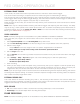
COMMUNICATION
The Communication screen allows you to set a unique identification for your camera (or a group of cameras)
when operating in a command and control communications network.
You can use the serial port or a direct Ethernet interconnect to connect two cameras, or one camera and one
external device. If the camera is connected via Ethernet to a hub or router, multiple cameras and devices can
communicate with each other.
The communication structure allows for a lot of flexibility. For example, on a multi-rig 3D shoot, you can either
send commands to an individual camera (Example: Set CAM_A_L to 1/48 exposure), to a group of cameras
(Example: Set “3DRIG_A” to 48 FPS), or to all cameras (Example: Start Recording on all cameras).
With the exception of the None setting, all command filtering happens on the receiver side of the communica-
tion link.
Name: Enter a unique camera name to use in network communications. The field is limited to eight (8) char-
acters.
Group: Enter a group name if you want to identify the camera as a member of a group of devices. For ex-
ample, a group “3DRIG_A” could include two cameras: “CAM_A_L” and “CAM_A_R”. Group names (like
camera names) can be used to uniquely address commands to a specific group of networked cameras. The
field is limited to eight (8) characters, and the default name is DEFAULT.
Target: Specify which devices the camera can send commands to:
‒ All: The camera can send commands to all devices on the network.
‒ None: The camera cannot send commands to any devices on the network. The camera can only receive
messages.
‒ Custom: The camera can send commands to a specific camera/device (enter the name of the camera/
device in the Custom text box) or a specific group (enter the name of the group in the Custom text
box). The camera or group name must match the name entered in the Name or Group field of the target
device(s).
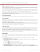
SERIAL PROTOCOL
The camera can communicate to external devices via the RS232 Serial Port and/or the Gigabit Ethernet Port.
Select one of the following protocols from the Serial Protocol drop-down menu:
None
Element Technica
3ality SPC 7100
3ality SPC 7000
Serial Shell (default)
RED Control Protocol
RCP 3D Metadata
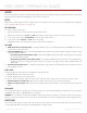
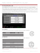
NETWORK
Use the settings on the Network tab to configure the Gigabit Ethernet port. Each camera or device requires a
unique IP address. For simple camera-to-camera communication via Ethernet, both cameras need to be in the
same sub-net (have the same netmask address) and have the same gateway address.
DHCP: Enables DHCP. If a DHCP-server is available in the communications network, the camera will obtain
an IP address, netmask address, and gateway address automatically from the DHCP server. You cannot
manually enter anything in the IP Address, Netmask, and Gateway fields when this check box is selected.