
Specifications

RED DSMC OPERATION GUIDE
COPYRIGHT © 2013 RED.COM, INC
955-0020_V5.1, REV-A | 31
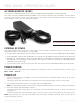
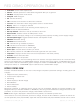
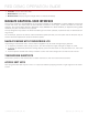
When connecting a cable to an auxiliary connector, align the key and red mark on the auxiliary connector with
the corresponding key on the cable connector.
PIN DESCRIPTION
1 Ground
2 +12VDC
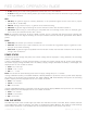
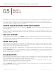
INSTALL BACKPACK QUICKPLATE AND RED BRICK
REQUIRED TOOL: T20 Torx
®
driver (for installing BACKPACK BASE PLATE only)
Both the BACKPACK QUICKPLATE and BACKPACK QUICKPLATE (SHORT) are installed using the same quick
and easy procedure described below.
1. Ensure that the BACKPACK BASE PLATE is properly attached to your DSMC with the four M4 mounting
screws.
2. Turn the BACKPACK BASE PLATE wingnut counter-clockwise by 2-3 turns.
3. Slide the BACKPACK QUICKPLATE dovetail into the BACKPACK BASE PLATE, so that the V-Mount on the
BACKPACK QUICKPLATE is facing away from the DSMC.
4. Secure the BACKPACK QUICKPLATE by turning the BACKPACK BASE PLATE wingnut clockwise until it
stops turning (do not over tighten).
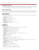
5. Slide the RED BRICK onto the back of the BACKPACK QUICKPLATE so that it fits into the V-Mount on the
back of the BACKPACK QUICKPLATE.
NOTE: You may not hear a click when the RED BRICK is fully connected.
6. Connect the BACKPACK QUICKPLATE LEMO connector into the DSMC DC IN connector.
7. When you’re ready to remove the RED BRICK, simply press the release button [the release button is black
on the BACKPACK QUICKPLATE and is red on the BACKPACK QUICKPLATE (SHORT)] on the side of the
BACKPACK QUICKPLATE.
2
1
Auxiliary Connectors
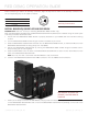
BACKPACK QUICKPLATE
(SHORT) and RED BRICK
Installed