
Specifications


RED EPIC OPERATION GUIDE
COPYRIGHT © 2013 RED.COM, INC
955-0002_v4.0, Rev-A | 194
APPENDIX G: REDMOTE OPERATION
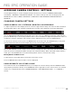
CONTROL, CONNECTORS AND DISPLAY
This section describes the REDMOTE physical controls, connectors and color LCD display.
CONTROLS
REDMOTE
A. Still/Motion Slider
B. Release Button (L)
C. Record LED
D. Power LED
E. Rocker Switch
F. User Keys A-D
G. MENU Button
H. Soft Menu Keys 1-3
I. Navigation Group
J. Focus/Record Button
K. Soft Menu Keys 4-8
L. Power/Lock Slider
M. Release Button (L)
N. USB Connector
STILL / MOTION SWITCH
The STILLS/MOTION toggle switch is used to switch between STILLS operation (DOWN) and MOTION
operation (UP). When the toggle switch is set to the MOTION position, all camera settings and defaults are
movie specific. When the toggle switch is set to the STILLS position, all camera settings and defaults are
stills photography specific.
NOTE: In Version 3.x software the STILLS/MOTION switch is disabled. Default mode is MOTION.
LEDS
There are two status LED indicators located above the rockers switch on the left side of the LCD display.
The upper LED is used to signal camera readiness and camera record status.
Red – Camera Startup / Camera Recording.
C
D
H
J
I
N
A
B
C
D
E
G
F
H
I
K
J
N
M
L