
Technical data


Version 3.0
955-0002_V3.0, REV-A ©2011-2012 RED.COM INC.
167
SYNC (VIDEO SYNC)
A 4-pin LEMO connector supports shutter synchronization input, GPI, timecode and genlock signals.
The shutter Sync Input signal acts as an immediate response hardware trigger to commence a scan.
This is useful for motion control and other applications where the camera is driven by a master timing
device. When using SYNC as the camera shutter timing reference, fine shutter start time timing
(SHUTTER PHASE) is disabled, make any timing adjustments at the external SYNC generator itself.
Alternatively, this input pin may be used as a GPI (General Purpose Input) trigger, whose function is
programmed in the USER KEYS menu. Default is Record Start / Stop.
A SMPTE timecode input signal provides a frame accurate time stamp for each frame of recorded video.
External TC must be chosen in the Project > Timecode menu. When SMPTE timecode is detected it will
align the internal TC at every :00 frame crossing to the external time.
A Video Genlock input signal may be used as a vertical interval reference signal for applications that
require precise synchronization between cameras, such as 3D and live broadcasts. When using
GENLOCK as the camera shutter timing reference, fine shutter start time timing (SHUTTER PHASE) may
be adjusted. The HD-SDI monitor output will automatically be synced to the genlock when the signal is
detected.
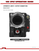
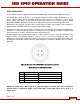
Figure 22: View into camera SYNC (Video Sync) Interface connector
Mating Connector: FGG.00.304.CLAD27Z
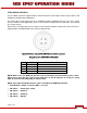
PIN SIGNAL DESCRIPTION
1 GROUND Common Ground
2 SS/GPI Shutter Sync / GPI Trigger Input
3 TIMECODE SMPTE unbalanced timecode Input
4 GENLOCK RS170A Tri-Level Sync Input
NOTE: The Shutter Sync / GPI Trigger uses a Schmitt trigger; 5 volt tolerant; 3.3v recommended.
Current must be supplied by trigger source. Both edges of the input signal can be used as a
trigger event.