
Technical data


Version 3.0
955-0002_V3.0, REV-A ©2011-2012 RED.COM INC.
163
MIC-1, MIC-2 (MICROPHONE AUDIO)
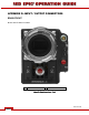
Two 3.5mm phone jacks on the front of the brain support two independent channels of balanced or
unbalanced analog microphone level audio inputs.
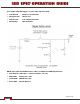
Figure 19: Microphone Input Connector
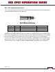
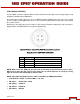
PIN SIGNAL DESCRIPTION DIRECTION
A (TIP) IN + Mic Input (+48V Phantom Power) In
B (RING) IN - Mic Input (+48V Phantom Power) In
C (SLEEVE) GND Camera ground --
Microphone Level analog audio input signals are routed via a high quality A/D and pre-amplifier, whose
Gain may be controlled using the Input Level control to achieve the desired audio reference / recording
level. Each microphone input supports +48V @ 10mA Phantom Power as a user selectable option.
To assist with reference level setup, the camera provides a color-coded Peak Level Meter in the
Graphical User Interface, with a solid vertical witness mark that indicates 0dBu / 0.775 v RMS /-20dbFS.
Peak Level Meter range is –36dBu to +20dBu (-54dBFS to 0dBFS) and provides input clip indication.
A
B
C