MINIMAG Operating Instructions (EN) MODELS: 17'' DISK PAD ASSIST 20'' DISK PAD ASSIST 23'' DISK PAD ASSIST 17'' DISK TRACTION 20'' DISK TRACTION 23'' DISK TRACTION 26'' DISK TRACTION 28'' DISK TRACTION 24'' CYLINDRICAL 20'' EDGE/ORBITZ 24'' EDGE/ORBITZ 28'' EDGE/ORBITZ Read these Instructions before using the machine. Read these Safety Messages before using the machine. www.rpscorporation.com www.factorycat.com www.tomcatequip.com © 2014 RPS Corporation VERSION 14.
INTRODUCTION This manual is furnished with each new machine. This manual will allow the Operator to get the best performance out of your RPS manufactured Scrubber-Drier, Sweeper, Burnisher, or Orbital Scrubber. Read this manual thoroughly before operating or servicing the machine. This machine will provide excellent performance, but the best results will be obtained at the most minimum costs if: • The machine is regularly maintained - per the machine Preventative Maintenance instructions provided.
TABLE OF CONTENTS Introduction 2 About This Manual 2 Table of Contents 3 Safety Messages 4 Safety Label Locations 6 LCD Screen Menu Displays: 7 Operation Controls - Pad Assist 8 Operation Controls - Traction 9 Tip Tank: Squeegee Up: Squeegee Down: Deck Height Adjustment: Vacuum Motor: Solution Filter: Cleaning Solution Filter: Battery Charging External Battery Charging: Machine Components 10 Machine Components 11 Machine Setup 12 Un-Crating Machine: Connecting Batteries: Adjusting Sq
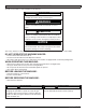
SAFETY MESSAGES You will see four kinds of safety reminders in this manual: DANGER DANGER indicates a hazardous situation which, if not avoided, will result in death or serious injury. WARNING WARNING indicates a potentially hazardous situation which, if not avoided, could result in death or serious injury. CAUTION CAUTION indicates a potentially hazardous situation which, if not avoided, could result in minor or moderate injury or damage to this machine or nearby objects.
WARNING The Batteries in this machine produce hazardous voltage which can cause electrical shock, burns and/ or electrocution. Always disconnect Batteries before servicing this machine. WARNING When climbing or descending ramps, always drive machine forward. To avoid overturning the machine, Do not back down ramps. Do not drive across inclines. Do not turn while ascending or descending ramps. Overturning the machine can cause serious injury or death. WARNING Do not use water that exceeds 135°F / 57°C.
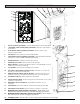
SAFETY LABEL LOCATIONS Read and obey all Safety Labels on your MINIMAG Floor Scrubber. If you have questions about these labels, ask your supervisor. These images indicate where on the MINIMAG Safety Labels are located. If ever the labels become illegible, worn off, or torn, promptly report it to your supervisor and replace it. DANGER EXPLOSION RISK! EXPLOSIVE HYDROGEN GAS FORMS WHEN BATTERIES ARE CHARGING. AN OPEN FLAME OR SPARK CAN CAUSE THIS GAS TO EXPLODE.
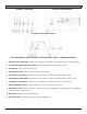
LCD SCREEN MENU DISPLAYS: SCREEN #1 (OPERATOR) SCREEN #2 (MAINTENANCE) SCREEN #3 (WITH ERROR CODE) ** USE GREEN MENU SELECTION BUTTON ON CONTROL PANEL TO CHANGE SCREENS ** 1. BATTERY LEVEL INDICATOR - Indicates the energy level remaining in the Batteries (Shown on all menu displays) 2. SCRUBDECK DOWN PRESSURE GAUGE - Sets the down pressure on the Brushes / Pads 3. VACUUM ON - Indicates the Vacuum is ON 4. SCRUB MOTORS ON - Indicates the Brush Motors are “running” 5.
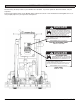
OPERATION CONTROLS - PAD ASSIST 6 7 8 9 10 5 11 12 4 3 2 13 1 1. CIRCUIT BREAKER: 40 AMP resettable circuit breaker 2. CIRCUIT BREAKER: 25 AMP resettable circuit breaker 3. CIRCUIT BREAKER: 2 AMP resettable circuit breaker 4. KEY SWITCH (OPTIONAL): Turns the machine ON and OFF 5. SQUEEGEE LIFT LEVER: Lowers and raises the Squeegee 6. MAIN POWER SWITCH: Turns the machine ON and OFF 7. BATTERY GAUGE / HOUR METER: Indicates the amount of battery charge remaining along with total hours used 8.
OPERATION CONTROLS - TRACTION 6 7 8 9 10 11 12 1 2 3 4 5 1. SPRAY JET [BLUE] (OPTIONAL): Activates Water Pump for remote Spray Wand 2. “ON-BOARD” SOAP SYSTEM [GRAY] (OPTIONAL): Dispenses soap directly to the deck level 3. ECON TOGGLE SWITCH [GREEN] (OPTIONAL): Reduces power to give machine a longer run time 4. KEY SWITCH: Turns power of the machine ON and OFF 5. LOAD TOGGLE SWITCH [ORANGE] (OPTIONAL): Engages different Scrubdeck parameters for increased RPM for Stripping and Polishing 6.
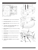
MACHINE COMPONENTS 2 3 1 1. TRACTION DRIVE: Propels machine forward/backward 4 2. SOLUTION FLOW VALVE: Controls solution flow rate 3. SOLUTION FILTER: Filters water solution prior to scrubbing 4. “PAD ASSIST” DRIVE ADJUSTMENT KNOB: Adjusts amount of offset being applied to Brush 5. WALL ROLLERS: Helps protect machine when scrubbing near walls 6. 5 6 CLEAR COVER: For viewing inside Recovery Tank area 7 7. RECOVERY LID: Used for flushing out Recovery Tank area with fresh water 8.
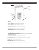
MACHINE COMPONENTS 1 11 2 3 4 10 5 6 7 8 9 1. CONTROL PANEL: Machine controls and access to electrical components 2. SOLUTION SIGHT GAUGE & DRAIN TUBE: Shows precise level of cleaning solution in Tank while also used as a Solution Tank drain hose 3. VACUUM HOSE: Creates vacuum for Squeegee (NOTE: Keep free and clear of blockage) 4. SQUEEGEE PITCH ADJUSTMENT: Adjusts pitch of Squeegee - Deflection should be even across entire blade 5.
MACHINE SETUP UN-CRATING MACHINE: Carefully check the crate for any signs of damage and that the batteries are in the unit. To un-crate the machine, remove banding strips from around the crate. Take off the top and sides and dispose properly. Remove brackets from machine wheels. Remove bolts from pallet, then remove board. Carefully roll the machine off of the base. Notify the carrier immediately if concealed damage is discovered.
ADJUSTING SQUEEGEE: 1. Turning adjustment knob (A) clockwise (tightening) will lower tips and raise the center of the Squeegee (SEE BELOW). REMOVING SQUEEGEE: 1. With the Squeegee in the up position, turn machine power off. 2. Disconnect Vacuum Hose (A) from squeegee and loosen both knobs (B) (SEE BELOW). A A 2. This Squeegee is adjusted too far back and will not pick up on the corners (SEE BELOW). NOTE: Tips off of the floor. B B 3. Pull Squeegee assembly backward from the lifting carrier. 4.
INSTALLING DISK PAD DRIVER OR BRUSH: 5. Attach Brushes or Pads to Motor Drives. Squeegee the scissor locking device and lift brush up on to the motor drive hub. Make sure the scissors close and lock one the Brushes are on (SEE BELOW). 1. Turn on machine power. 2. Raise the Scrubdeck by depressing the Brush switch to the up and OFF position and turn the machine power back off. Remove Key. 3. If the machine is equipped with Jaws, remove pin (A) and undo latch (B) on front of Jaws to open them (SEE BELOW).
INSTALLING CYLINDRICAL BRUSH: 7. Brush Drivers shown misaligned (SEE BELOW). 1. Turn on machine power. 2. Raise the Scrubdeck by depressing the Brush switch to the up and OFF position and turn machine power back off. Remove Key. CAUTION Disconnect the batteries. OLD STYLE DRIVER 3. Remove side access door on each side of the Scrubdeck by depressing latch (A) and unscrewing the Thumb Screw (B) (SEE BELOW). NEW STYLE DRIVER 8. Brush Driver shown properly aligned (SEE BELOW). 4.
INSTALLING EDGE/ORBITZ PADS: LEVELING EDGE/ORBITZ DECKS: 1. Turn on machine power. NOTICE 2. Raise the Scrubdeck by depressing the Brush switch to the UP and OFF position and turn machine power back off. All Scrubdeck’s should be level at time of machine delivery. If machine Scrubdeck is not level - Contact your Servicing Dealer. 3. Select the correct Pads that best meet your cleaning application. Consult your local dealer for assistance. 1. Drive machine to a flat level surface and turn machine off.
LEVELING DISK DECKS: LEVELING CYLINDRICAL DECKS: NOTICE NOTICE All Scrubdeck’s should be level at time of machine delivery. If machine Scrubdeck is not level - Contact your Servicing Dealer. All Scrubdeck’s should be level at time of machine delivery. If machine Scrubdeck is not level - Contact your Servicing Dealer. All Single-pad Scrubdecks have Adjustable Deck Arms to allow the operator to lessen the torque that may develop from the Single-pad Scrubdeck.
MACHINE OPERATION PRE-CLEANING CHECKLIST: OPERATING HINTS: Read and understand the Safety Messages section on Pages 3 and 4 before operating the machine. 1. Observe the amount of solution the machine is dispensing on the floor and adjust to the desired flow. To increase the solution flow rate, press the Solution Control Toggle up. To shut the solution OFF completely, just release the Drive button, or use dash mounted switch. 1. Check Battery Condition Gauge on the Control Panel.
ONE PASS SCRUBBING (PAD ASSIST): SCRUB ONLY: 1. Turn on machine Power Switch (A) (if machine is equipped with optional Key Switch), make sure the Pad Assist Adjustment Knob (B) is at a lower setting. 1. Turn ON machine Power Switch (A) while making sure the Pad Assist adjustment knob (B) is at a lower setting. 2. Lower the Squeegee by rotating the Squeegee Lift Lever (C) all the way to the right (the Vacuum Motor will turn on automatically). 2.
ONE PASS SCRUBBING (TRACTION): SCRUB ONLY: 1. Turn on machine Power Switch (A), make sure the Speed Control Knob (B) is at a lower setting. 1. Turn on machine Power Switch (A) while making sure the Speed Control Knob (B) is at a lower setting. 2. Lower the Squeegee by rotating the Squeegee Lift Lever (C) all the way to the right (Vacuum Motor will turn on automatically). 2. Lower Scrubdeck head to the floor by pressing the Scrubdeck Switch on the Control Panel (D) 3.
ADJUST SOLUTION FLOW: 1. Push UP (+) on the Solution Flow Toggle (A) to increase the solution flow and push DOWN (-) on the toggle to decrease solution flow (SEE BELOW). A DRAINING SOLUTION TANK: To drain unwanted cleaning solution from the Solution Tank, perform the following steps: (SEE BELOW) 1. Pull the clear Sight Tube/Drain Hose (F) off barbed fitting. 2. Rinse out Tank and solution flow system with clean water. ADJUST CURTAINS: F 1.
OPEN RECOVERY LID: 1. Release both latches (A) on Recovery Tank lid (SEE BELOW). NOTICE Keep water off of Control Panel. CLEAN “DRAIN SAVER”: With Recovery Lid open and Tank fully drained: 1. Remove 2'' Squeegee intake hose (D) from “Drain Saver” strainer (E) (SEE BELOW). 2. Remove stainless screen and dispose of debris. A 3. Rinse screen with fresh water from the outside while holding the screen upside down. This will allow for better cleaning. 4. Replace the screen into the bracket. 5.
TIP TANK: 1. Fully drain Solution Tank and the Recovery Tank. 2. Remove Squeegee. 3. Unlatch Tank Latch (A) on each side of the machine (SEE BELOW). SQUEEGEE UP: 1. To raise the Squeegee off the floor, rotate Squeegee Lift Lever (C) counter-clockwise all the way to the left (SEE BELOW). C A B CAUTION Casters need to be swiveled back (B) as shown, otherwise machine will tip. 4. Open Jaws (SEE BELOW). SQUEEGEE DOWN: 1.
DECK HEIGHT ADJUSTMENT: SOLUTION FILTER: 1. To adjust deck height for Brush / Pad clearance, loosen jam nut on adjustment bolt (A), turn adjustment bolt clockwise to raise Scrubdeck - counterclockwise to lower Scrubdeck. Retighten jam nut (SEE BELOW). The solution system has an “Inline Filter” (F) to filter out cleaning solution prior to scrubbing (SEE BELOW). A F VACUUM MOTOR: 1. The machine is equipped with a 24 volt, .75HP Vacuum Motor (B) (SEE BELOW). 2.
BATTERY CHARGING Charger Specifications • Output voltage of 24 Volts • Output current of 18 amps max (Optional) • Input voltage of 110 Volts/ 60 Hz (220V/50 Hz available) • Automatic shut off circuit • Made for Deep Cycle Batteries DANGER is connected, plug the charger power cord into a grounded 110 Volt standard wall outlet (C). 5. The Charger will automatically begin charging and automatically shut off when fully charged (check Battery gauge). 6.
ON-BOARD CHARGER Charger Specifications • Output voltage of 24 Volts • Output current of 12 amps max • Input voltage of 110 Volts/ 60 Hz (220V/50 Hz available) • Automatic shut off circuit • Made for Deep Cycle Batteries DANGER wall outlet (B). 5. The green Indicator Light (C) will come on and the Charger will automatically begin charging. When finished, the Charger will automatically shut off as well as the green indicator light (check Battery gauge). 6.
BATTERY MAINTENANCE GUIDE SAFETY: WATERING: DANGER Explosive hydrogen gas forms when Batteries are charging. An open flame or spark can cause this gas to explode. Serious personal injury or property damage could occur. Only charge the Batteries in this machine in a well ventilated area. WARNING Before you service a Battery, always wear face protection, protective gloves and protective clothing. Battery acid or battery explosion can cause serious injuries.
MAINTENANCE DAILY MAINTENANCE: if needed, 8-10 ft/lb MAX. 1. Remove the clean Pads or Brushes. Never use soiled Pads when cleaning. Replace Pads when they become packed with residue. 4. Grease caster swivel and squeegee pivot point. 2. Remove and clean debris from the float shut-off screen and Drain Saver located inside the Recovery Tank. Call your local dealer for yearly maintenance. 3. Drain and rinse Tanks thoroughly and flush out Solution Feed to deck. 4.
MINIMAG PM RECORDS CUSTOMER INFORMATION CUSTOMER EMAIL ADDRESS CITY PHONE STATE ZIP CONTACT MACHINE INFORMATION MODEL #: SERIAL #: WORK ORDER#: HOUR METER (Key): CHASSIS HOUR METER: HOUR METER (Traction): RE-CHARGE COUNTER: HOUR METER (Scrub): ISOLATOR HOUR METER: HOUR METER (Vac): NOTE: Isolators need to be replaced on Scrubber Machines at 1000 Hours or Annually BATTERY CONDITION CELL 1 CELL 2 CELL 3 CELL 4 CELL 5 CELL 6 BATTERY 1 HYDROMETER BATTERY 1 ELECTROLYTE CLARITY (Clear, Clou
SQUEEGEE LIFT SYSTEM SQUEEGEE ADJUSTMENT PITCH AND HEIGHT SQUEEGEE BLADES DRAIN HOSE AND PLUG SIDE BROOM OPERATION SPRAY JET PUMP, HOSE & NOZZLE BATTERY CHARGER CONNECTION & FUNCTION PITCH OF SCRUBDECK (MUST BE LEVEL) PITCH OF EDGE/ORBITZ DECK (MUST BE LEVEL) CLEAN AND / OR LUBRICATE IN SPEC REPAIR PROBLEM IN SPEC REPAIR PROBLEM SOLUTION TANK CONDITION SQUEEGEE PIVOT POINTS & KNOBS SOLUTION FILTER CLEANING SCRUB DECK LINKAGE VISUALLY INSPECT SOLUTION TANK CONDITION RECOVERY TANK & GASKET CONDITION
TROUBLE-SHOOTING PROBLEM CAUSE SOLUTION NO POWER - NOTHING OPERATES FAULTY POWER SWITCH CONTACT LOCAL SERVICING DEALER BATTERIES NEED CHARGING SEE CHARGING BATTERIES FAULTY BATTERIES REPLACE BATTERY LOOSE BATTERY CABLE TIGHTEN LOOSE CABLE MAIN CIRCUIT BREAKER TRIPPED WAIT 5 MINUTES FOR AUTO RESET DETERMINE CAUSE AND CORRECT GREEN DRIVE BUTTON IS NOT DEPRESSED DEPRESS BUTTON ON HANDLE BAR CIRCUIT BREAKER TRIPPED RESET & REDUCE PRESSURE FAULTY SCRUBDECK MOTOR OR WIRES CONTACT LOCAL SERVICIN
PROBLEM CAUSE SOLUTION POOR WATER RECOVER ON TURNS WIPERS WORN REPLACE WIPER MATERIAL WIPERS CHATTER TIGHTEN PIVOT POINTS SQUEEGEE SWING IS BINDING CONTACT LOCAL SERVICING DEALER INCORRECT SQUEEGEE SIZE CONTACT LOCAL SERVICING DEALER BEARING DRY GREASE BEARINGS FAULTY HUBS CONTACT LOCAL SERVICING DEALER EXCESSIVE BRUSH PRESSURE REDUCE PRESSURE WITH SWITCH WORN DRIVE TIRE REPLACE TIRES HEAVY SOAP CONCENTRATION CONTACT LOCAL SERVICING DEALER BATTERIES RUN DOWN CHARGE BATTERIES TWICE BA
TROUBLE-SHOOTING CENTRAL COMMAND NOTE: This machine is operated by a sophisticated electronic “controller” that has many fail safes within it. It self-analyzes problems and flashes a four-digit alpha-numeric code of what is wrong in the LCD window. Most of these codes require a technician attention. You should not attempt repairs you are unfamiliar with, especially if you are not authorized to work on this equipment. 1. 7601 and 7602 ERROR: Scrubdeck current over load.
5. 7700: Vacuum Motor circuit is open. 6. Throttle ERROR: You pressed the foot pedal before turning on the Key. Turn off the Key and try again, leaving foot off of the pedal. 7. 2C00 and 2C01 ERROR: Low voltage warning. Voltage has dropped down below the minimum required to operate the machine. If you wait a few minutes, the Batteries may come up in voltage, allowing you to drive very slowly to the recharge station.
MACHINE SPECS BODY CONSTRUCTION/DIMENSIONS MINIMAG (PAD ASSIST) TANK MATERIAL: CHASSIS CONSTRUCTION: FRONT WHEELS: REAR CASTERS: SIZE (L × W × H): WEIGHT (WITHOUT BATTERIES): WEIGHT (WITH BATTERIES): POLY (3⁄8'') (.9525 cm) 3 ⁄16'' STEEL (.2 cm) (2×) 9''×2'' [(2×) 23×5 cm] (2×) 4''×2'' [(2×) 10 × 5 cm] 45''×18''×40'' (114×46×102 cm) 242 LB. 374 LB. MINIMAG (TRACTION) POLY (3⁄8'') (.9525 cm) ⁄16'' STEEL (.
COMMON WEAR PARTS ROUND DISK BRUSHES: BRUSHES MODEL 17'' MODEL 20'' MODEL 23'' DISK DISK DISK MODEL 26'' DISK MODEL 28'' DISK Super Grit 17-421SS 20-421SS 23-421SS 13-421SS 14-421SS Tough Grit 17-421S 20-421S 23-421S 13-421S 14-421S Midi Grit 17-421C 20-421C 23-421C 13-421C 14-421C Light Grit 17-421PS 20-421PS 23-421PS 13-421PS 14-421PS Poly (.028) 17-421P 20-421P 23-421P 13-421P 14-421P Nylon (.
36 Grit Sand Paper N/A N/A EDGE-4032 N/A 60 Grit Sand Paper N /A N/A EDGE-4033 N/A 80 Grit Sand Paper N/A N/A EDGE-4034 N/A 100 Grit Sand Paper N/A N/A EDGE-4035 N/A 100 Grit Diamond Polishing Pad N/A N/A EDGE-4012 N/A 400 Grit Diamond Polishing Pad N/A N/A EDGE-4013 N/A 800 Grit Diamond Polishing Pad N/A N/A EDGE-4014 N/A 1500 Grit Diamond Polishing Pad N/A N/A EDGE-4015 N/A 3000 Grit Diamond Polishing Pad N/A N/A EDGE-4016 N/A 6000 Grit Diamond Polishing Pad N
SQUEEGEE SIZE GUM RUBBER LINATEX BLADE KIT BLADE KIT COMPLETE SQUEEGEE ASSEMBLIES 32'' Squeegee 22-770G 22-770L 22-770U 23-7180 35'' Squeegee 25-770G 25-770L 25-770U 25-7180 NOTICE Squeegee blade kits include (1) Rear Blade, (1) Front Blade, and (2) Backup Wheels with hardware. NOTICE Size is stamped into the top of the painted steel squeegee body on all squeegee's. - 38 - URETHANE BLADE KIT NOTICE Squeegee Assemblies (complete) listed above all come with Linatex blades.
SOAP CHOICES Industrial • Commercial • Environmentally Safe TRADITIONAL DRUMS / TOTES DEMO / RENTAL QUARTS WALL-MOUNTED SUPERCON ONBOARD AUTO DISPENSING MINIMAG-OP-EN - 39 -
Onboard Availability FORMULAS 707 Citrus Green An environmentally cleaner that works! It is a solvent free degreaser that works on oil, carbon, even rubber marks. Incorporates the latest technology in “Green Cleaning”. DS SUproved Ap 733 Low pH Safe on most surfaces not harmed by water alone. Low scale formula to prevent alkali buildup in cleaning equipment, while offer detergent to emulsify oil. 755 High Power Ideal solvent fortified degreaser.
STANDARD WARRANTY POLICY RPS Corporation warrants its Machines and Original Equipment Accessories to be free of manufacturer’s defects in materials or workmanship for the periods specified below. Warranty will be granted at the sole discretion of RPS Corporation and is subject to final claim and parts review by RPS Corporation and its vendors. This policy is effective January 1, 2014 and is subject to change on production units at a future date.
MACHINE INSTALL / WARRANTY REGISTRATION Installing Dealer: Installed By: Location: (City, State): Install Date: End-User Company Name: End-User Contact: Address: City/State: Zip: Phone: Fax: Email: Model: Serial #: Hour Meter: BUYER’S REPRESENTATIVE HAS RECEIVED INSTRUCTION IN PROPER OPERATION OF THE FOLLOWING CONTROLS AND FEATURES: SCRUBBERS: - Filling solution tank, Solution tank sight tube, Solution drain hose or valve for flushing and freezing conditions - Adjusting controls & operation,
BLANK THIS PAGE WAS INTENTIONALLY LEFT BLANK
1711 South Street Racine, WI 53404 www.rpscorporation.com www.factorycat.com www.tomcatequip.com Tel. US: 800-634-4060 Tel.