www.regency-fire.com www.excalibur-fire.com www.hampton-fire.com U31 Gas Insert Owners & Installation Manual MODELS: U31-NG2 Natural Gas U31-LP2 Propane FOR YOUR SAFETY WARNING: If the information in these instructions are not followed ex- What to do if you smell gas: Do not try to light any appliance actly, a fire or explosion may result causing property damage, Do not touch any electrical switch: personal injury or loss of life. do not use any phone in your buildFOR YOUR SAFETY ing.
FPI GAS FIREPLACE INSERT TO THE NEW OWNER Congratulations! You are the owner of a state-of-the-art Gas Insert by FPI. The FPI Gas Insert Series of hand crafted appliances has been designed to provide you with all the warmth and charm of a fireplace, at the flick of a switch. The models U31-NG2 and U31-LP2 of this series have been approved by Warnock Hersey for both safety and efficiency.
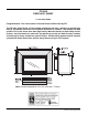
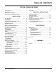
TABLE OF CONTENTS FPI GAS FIREPLACE INSERT Unit Dimensions ........................................................2 Safety Label ..............................................................4 MA Code - CO Detector (for the state of Massachuettes only) ........................5 INSTALLATION For Your Safety ..........................................................6 Specifications ............................................................6 Installation into a Solid Fuel Fireplace .......................
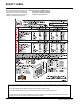
SAFETY LABEL This is a copy of the labels that accompany each U31-2 Gas Insert. We have printed a copy of the contents here for your review. The safety label is located on a plate inside the base of the unit visible when the bottom louver is opened. NOTE: FPI units are constantly being improved. Check the label on the unit and if there is a difference, the label on the unit is the correct one.
REQUIREMENTS MA Code - CO Detector (for the State of Massachusetts only) 5.08: Modifications to NFPA-54, Chapter 10 (2) Revise 10.8.
INSTALLATION IMPORTANT: SAVE THESE INSTRUCTIONS The FPI Gas Insert must be installed in accordance with these instructions. Carefully read all the instructions in this manual first. Consult the building authority having jurisdiction to determine the need for a permit prior to starting the installation. NOTE: Failure to follow the instructions could cause a malfunction of the heater which could result in death, serious bodily injury, and/or property damage.
INSTALLATION 11) Failure to position the parts in accordance with the diagrams in this manual or failure to use only parts specifically approved with this appliance may result in property damage or personal injury. 12) Due to high temperatures, the appliance should be located out of high traffic areas and away from furniture and draperies.
INSTALLATION Conversion Kit from Natural Gas to Propane Model #402-969 for: U31-NG2 Units THIS CONVERSION MUST BE DONE BY A QUALIFIED GAS FITTER IF IN DOUBT DO NOT DO THIS CONVERSION !! 1) Turn the unit off and allow it to cool to room temperature. 8) Remove regulator from valve and replace with Propane regulator. See diagram 1. 2) Unplug or disconnect power source to stove.
INSTALLATION Before installing vent system ensure that the damper plate is open and secure to prevent the damper plate from falling down and crushing the liner. The manifold pressure is controlled by a regulator built into the gas control, and should be checked at the pressure test point. The pressure check should be carried out with the unit burning and the setting should be within the limits specified.
INSTALLATION 3) After five minutes, test that there is a “pull” on the flue by placing a smoke match, cigarette or similar device which gives off smoke, in front of the spill tube. To ensure a valid test, place a scrap piece of sheet metal (or other noncombustible material) between the spill tube and the upper louver, this will prevent the natural convection of the unit from interfering with the test. See diagram 1.
INSTALLATION 6) Place the Left Top Log D)02-46 on the pin on Log C)02-56 and on top of the cutout on Log A)02-43. A)02-43 B)02-45 3) Place Rear Log A)02-43 on the two pins on the rear log support. F)02-48 A)02-43 D)02-46 Side View A)02-43 Front edge of rear burner Bracket C)02-56 The bottom right edge of Log F)02-48 must sit snugly against the bracket and the front edge of the rear burner. Pins on Rear Log Support Pin 4) Place Front Right Log B)02-45 on the two pins as shown.
INSTALLATION FACEPLATE & TRIM INSTALLATION 1) Lay the faceplate panels flat, face down on something soft so they don't scratch. 2) Take the top faceplate and align the holes in it with the holes in the side panels. Using the screws provided, attach from the top of the panel (the holes in the top panel are slightly larger than the holes in the side panel to facilitate easier installation). Diagram 1.
INSTALLATION 3) Place the bottom of the flush glass behind the bottom glass trim. 4) Secure the glass with the two glass clips at the top corners of the glass. Secure glass clips with the screws provided. Do not over tighten as this could break the glass. BAY FRONT INSTALLATION 1) Place the bay door onto the 2 pins on the top of the unit. BAY LOUVERS 1) Install top louver by sliding the two bracket clips into the brackets located on top of the bay door. See below.
INSTALLATION 3) Open Bottom Louvers. Insert Screen Door hooks into the 4 slots between the faceplate and the flush door. 4) Remove the bottom glass trim. Discard both top & bottom glass trim. 5) Replace the glass and secure with the two glass clips. Do not over tighten as this could break the glass. Slots Make sure the glass is centered. Side Hook 6) Insert side hooks on the double screen door into the 4 slots between the faceplate and the glass and lower assembly into the locking position.
INSTALLATION FULL SCREEN FRONT 1) Hold the full screen door up against the unit in order to make the following wire connections. 3) Completely secure the full screen door to the unit by securing 4 screws to the Left and Right Side Trims. Pull the ON/OFF connector wires from the firebox and connect them to the switch. Connect the fan switch wires with the wire connectors from the fan speed control. Place clips over wires and tuck into side trim. .
INSTALLATION 4) Install Spring Hinges on the Left and Right Side of the bottom of the firebox using 2 screws per hinge. 7) Install the Left and Right Side Screen Doors in the fully open position by placing over top of the hinges on the full screen door. Hinge 5) Place Bottom Frame near hinge. Flip hinge over Bottom Frame and secure with 3 screws. Hinge Location Screen Door Bottom Frame 8) Close screen doors.
INSTALLATION HAMPTON CAST FACEPLATE INSTALLATION NOTE: Do not install Cast Faceplate when unit is installed into a Zero Clearance Unit. 1) Lay the faceplate panels flat, face down on something soft so they don't scratch. 2) Attach the side filler brackets to the left and right sides using 3 screws and washer per side. NOTE: There are filler brackets specifically for each side. The way to differentiate this is that on the side of the brackets there are 2 mounting holes.
INSTALLATION 11) Mount the cast faceplate panels onto the insert body, sliding the side filler brackets into the space between the glass and the firebox. Secure using the 4 remaining black screws, 2 per side. Slide side filler bracket into gap between glass and fire box. HAMPTON CAST FACEPLATE GRILL INSTALLATION Before the grills are installed, a grill stop bracket needs to be put in place.
INSTALLATION EXCALIBUR SURROUND INSTALLATION IMPORTANT NOTE: When using the Surround, the unit must be set 1" further into the fireplace than the standard faceplate installation. See the diagrams below for the correct minimum fireplace opening requirements. 2) Align the cut-outs in the Blanking Plate with the pins located on the inside top of the firebox. Slide the Blanking Plate into position ensuring it goes under the 2 flanges.
INSTALLATION 4) Secure the Faceplate by sliding the slots in the Faceplate into the flanges on the left and right side Faceplate Trim Brackets. Once the Faceplate is in place secure using 2 screws per side. 5) Place the bottom hooks of the Surround into the bottom slots of the Faceplate. Slightly pull up the Surround and push the top hooks into the top slots of the Faceplate. Push down to secure. Tug on the Surround to ensure it is securely locked in place.
OPERATING INSTRUCTIONS OPTIONAL WALL THERMOSTAT A wall thermostat may be installed if desired. Connect the wires as per the wiring diagrams. Note that the wires are connected to the "TH" on the gas valve. Use table on page 14 to determine the maximum wire length: Note: Preferable if the thermostat is installed on an interior wall. FPI offers an optional programmable thermostat but any 250-750 millivolt rated non-anticipator type thermostat that is CSA, ULC or UL approved may be used.
OPERATING INSTRUCTIONS SHUTDOWN PROCEDURE 1) Use the rocker switch to turn off the main burner. 2) Open the bottom louver assembly. 3) Push in the gas control knob slightly and turn clockwise to "OFF". Do not force. 4) Disconnect all electric power and gas to the appliance if service is to be performed. FIRST FIRE The first fire in your stove is part of the paint curing process.
MAINTENANCE are temperature changes within the unit these sounds will likely re-occur. Again, this is normal for steel fireboxes. 5) Keep the area near the appliance clear and free from combustible materials, gasoline and other flammable vapours and liquids. Blower Thermodisc: When this thermally activated switch turns ON it will create a small "clicking" sound. This is the switch contacts closing and is normal.
MAINTENANCE DOOR GLASS REPLACEMENT Your FPI insert is supplied with high temperature, 5 mm Neoceram ceramic glass that will withstand the highest heat that your unit will produce. In the event that you break your glass by impact, purchase your replacement from an authorized FPI dealer only, and follow our step-by-step instructions for replacement. WARNING: do not operate appliance with the glass front removed, cracked or broken.
PARTS LIST Main Assembly Part # Description 1) 400-011 Fan Opening Cover 400-515/P 2) 910-331/P 5) 910-750 910-752 Fan Assembly (120 V) Fan Motor (120 V) Power Cord (120 V) Wire Harness (intermediate) 6) * 7) * 8) 910-142 10) 400-540 11) * 12) 910-220 13) * 16) * 17) * 18) * 19) * 20) 400-024 Thermodisc cover Thermodisc bracket Thermodisc-Fan Auto ON/OFF Drafthood Assembly Spill Switch Bracket Spill Switch Levelling Bolts 5/16 x 3 Hex Head Cable Tie Wire Holder Clip Strain Relief Grommet for Power Co
PARTS LIST Burner Assembly & Log Set Part # 52) 53) 54) 55) 56) 402-560/P 402-562/P 910-028 910-029 910-190 * 904-702 * Description Valve Assembly - NG Valve Assembly - LP Robertshaw Valve -Nat. Gas Robershaw Valve - LP Piezo Ignitor and nut Valve Heat Shield Fibre Washer Pilot Bracket 57) 904-240 904-593 904-390 904-345 60) 402-526 Burner Orifice Nat. Gas #37 Burner Orifice Nat. Gas #40 (High Altitude) Burner Orifice LP # 52 Burner Orifice Nat.
PARTS LIST Bay & Flush Front Assembly Part # Bay Door 400-988 102) * 103) * 106) 940-315/P 107) 936-243 108) 940-314/P 110) 902-183 402-905 402-906 111) * 112) 904-196 Description Bay Door c/w Black Trims Glass Retainer Side Glass Retainer Front Side Glass Gasket - Adhesive Backing Center Glass Bay Brick Panel - Standard Bay Brick Panel - Standard Brown Bay Brick Panel - Standard Red Door Trim 1" Round Magnet 910-424 910-426 Extension Knob - Pilot ON/OFF Extension Knob - Flame HI/LOW 402-956 402-958 Go
PARTS LIST Faceplate Assembly Part # Description 402-919 41) * 42) * 43) * 402-534 44) * 45) * 46) * Complete Faceplate (Set) with Black Trim - Oversize Faceplate Side Right - Oversize Faceplate Top - Oversize Faceplate Side Left Assy-Oversize Trims Pkg.
PARTS LIST FPI U31-2 Gas Fireplace Insert 29
PARTS LIST HAMPTON CAST FACEPLATE ASSEMBLY Part # 402-971** Description Cast Faceplates (Set) 187) 910-246 188) 910-330 189) 904-733 Burner On/Off Switch Fan Speed Control (120 V) Knob - Black Cast Surround 201) * 202) * 203) * 205) * 194) * Cast Faceplate - Right Cast Faceplate - Top Cast Faceplate - Left Flush Glass Frame Mounting Flange 207) 402-981** Cast Grill (Set) - Top & Bottom *Not available as a replacement part.
WARRANTY FPI Fireplace Products are designed with reliability and simplicity in mind. In addition, our internal Quality Assurance Team carefully inspects each unit thoroughly before it leaves our facility. FPI Fireplace Products International Ltd. is pleased to extend this limited lifetime warranty to the original purchaser of a FPI Product. This warranty is not transferable.
FPI fireplaces are designed with reliability and simplicity in mind. In addition, our internal Quality Assurance Team carefully inspects each unit thoroughly before it leaves our door. FPI Fireplace Products International Ltd. is pleased to extend this Limited Lifetime Warranty to the original purchaser of a FPI Product. See the inside back cover for details. Register your Regency online at http://www.regency-fire.com Register your Hampton online at http://www.hampton-fire.