
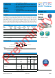
Datasheet


www.recom-power.com
REV.: 0/2019 RPMB-6
DC/DC Converter
Specifications (@ Ta= 25°C, nom. Vin= 24VDC, full load, with input cap
(3)
, after warm-up unless otherwise stated)
RPMB-2.0
Series
DIMENSION AND PHYSICAL CHARACTERISTICS
Parameter Type
Value
Material
case
PCB
solder pads
metal
FR4, (UL94 V-0)
copper with electrolytic nickel-gold
Dimension (LxWxH) 12.19 x 12.19 x 3.75mm
Weight 1.1g typ.
SAFETY AND CERTIFICATIONS
Certificate Type (Safety) Report / File Number Standard
RoHS2 RoHS 2011/65/EU + AM2015/863
EMC Compliance Condition Standard / Criterion
Electromagnetic compatibility of multimedia equipment - emission requirements
(8)
with external components
(see filter suggestions below)
EN55032, Class B
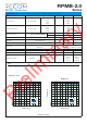
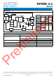
EMC filtering suggestion according to EN55032
V
in
GND1
GND3
GND2
NC
Trim
PG
Sense
V
out
CTRL
C
1
C
2
C
3
C
4
(3)
C
5
L
1
+V
in
+V
out
Component List Class B
C1, C2, C3, C4 L1 C5
10µF 50V X7R, 1210 2.2µH shielded inductor 10µF 25V X7R, 1206
Notes:
Note8: 4.7µF input capacitor (Note3) is not required if using EMC filter suggestion
1
A
B
C
D
E
2 3 4 51
A
B
C
D
E
2 3 4 5
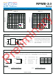
tc
11.70 11.70
12.19
±0.5
1.025 x
R0.3
3.75
1.06
1.06
Top View
1.52
12.19
±0.2
2.29
1.52
Bottom View
Recommended Footprint Details
Dimension Drawing
(mm)
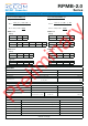
Pinning information
Pad # Function
Description
A1, A2 Vin
Positive input voltage with respect to GND. Connect to a Vin plane
for enhanced thermal performance
C1 CTRL
Active High: pull to GND to disable the device.
Pull high or leave open to enable the device
A5, B5 Vout
Positive output voltage. Connect to a Vout plane for enhanced
thermal performance
C5 Sense
Connect this pad to the load or directly to Vout.
This pad must not be left floating
E5 Trim
Used to set the output voltage between 1V and 24V,
leave open if not used
E2 NC
Not connected, leave open or connect to GND
E1 NC
Not connected, leave open or connect to GND
D1 PGood
Output power good. HIGH = power OK, LOW = power bad.
PG pulls low when CTRL = LOW.
PG HIGH when VOUT is between 95% and 107% of nominal (VOUT
rising) or when between 105% and 93% (VOUT falling) of nominal –
typical values. PG delay is typically 110us (
±
50%).
Maximum sink current is 5mA. Open drain output internally tied to
5V (typical) reference through 100kW resistor. Float if not used.
others GND
Negative input voltage. Connect to GND plane(s) for enhanced
thermal performance
tc = case temperature measuring point
Pad tolerance= ±0.05mm
Case tolerance= ±0.25mm
Preliminary