
Data Sheet

www.recom-power.com
REV.: 5/2019 I-6
DC/DC Converter
Specifications (measured @ Ta= 25°C, 10% minimum load, unless otherwise stated)
R-78AA-0.5
Series
INSTALLATION AND APPLICATION
continued on next page
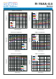
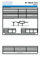
10 9 8 7 6
10 9 8 7 6
1 2 3 4 5
1 2 3 4 5
Bottom View
Top View
0.50
±0.05
15.3
15.0
2.54 x 4
9.4
9.68.812.35
9.24
13.00
1.30 1.202.54
1.80
10 9 8 7 6
10 9 8 7 6
1 2 3 4 5
1 2 3 4 5
Bottom View
Top View
0.50
±0.05
15.3
15.0
2.54 x 4
9.4
9.68.812.35
9.24
13.00
1.30
1.20
2.54
1.80
Dimension Drawing (mm)
Recommended Footprint Details
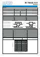
Pinning information
Pin # Single
1,2 +Vin
3,7,8,9 GND
4,5 +Vout
6 Vadj
10 CTRL
Tolerance:
xx.x= 0.5mm
xx.xx= ±0.25mm
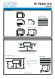
+V
in
+V
out
R
down
R
up
GNDGND
To protect the converter from high inrush currents, use soft start Vin and C1 = 10µF
Output capacitor C2 recommended if load is very dynamic
CTRL
R-78AAxx-0.5SMD
C1
100µF
(optional)
10µF
(optional)
C2
+V
in
+V
out
GND V
adj
CTRL
Standard Application Circuit
Pin Connections
Pin # Negative Positive
1,2 +Vin +Vin
3,7,8,9 -Vout GND
4,5 GND +Vout
6 -Vadj +Vadj
10 CTRL CTRL
Positive to Negative Converter
C1 and C2 are required and should
be fitted close to the converter pins.
Maximum capacitiv load including
C2 is 220µF
+V
in
GND
-V
out
R
down
R
up
GND
On/Off
(reference to -Vout)
R-78AAxx-0.5SMD
C1
C2
+V
in
-V
out
GND
-V
adj
CTRL