
Installation Guide

REC TwinPeak Installation Manual - IEC /
Rev E . Ref: NE
CONNECTIONS AND CONNECTORS
The connectors on REC TwinPeak panels are rated IP only when connected. All connectors and cables must be secure and tight as well as
electrically and mechanically sound. UV-resistant cables and connectors approved for outdoor use must be used. Conductor gauge must be
chosen to ensure DC power losses (voltage drop) are kept to a minimum (<).
Observe all local regulations when selecting cables. For string connections, use minimum mm
or copper wires insulated for a maximum
operating temperature of °C. Secure cables using UV-resistant cable ties or other device. Loose and unsecured cables must be protected
from damage (e.g., mechanical, abrasion, sharp objects, animals). Avoid exposing cables to direct sunlight and permanent tension.
In order to ensure durable and safe connections between panels and BOS equipment, the following instructions must be followed in order
to protect the electrical connections from the elements. More detailed information is given in the Guide to Best Practice - Connections and
Connectors which can be found via the REC online Download Center (www.recgroup.com/downloads).
Safety is paramount when working with electrical connectors. Ensure that any installation work is not carried out on live or load-carrying
parts. Connections must not be disconnected under load and the system must be isolated from the grid before carrying out any maintenance
or repair work.
CONNECTORS
To ensure connector compatibility and reduce the potential for damage to the solar modules and wider installation, REC recommends that
mated connectors are from the same manufacturer and of the same connector type. REC factory installed connectors are of the ‘MC type’
design. This means that REC only permits the mating of factory-installed connectors to connectors of the same manufacturer and type and to
Multi-Contact MC connectors.
Some countries and/or regions have specific regulations regarding the mating of connectors. Installers are responsible for ensuring
the compliancy of the system with such local regulations.
REC factory installed connectors are of the ‘MC4 type’ design. This means that REC only permits the mating of factory-installed
connectors to connectors of the same manufacturer and type and to Multi-Contact MC4 connectors.
Excepting the replacement of a factory-installed connector with a third brand of connector to ensure a ‘like-for-like’ connection,
the REC warranty will be voided by any modification to the cable and/or connector. The connector replacement procedure must be
carried out correctly and according to the replacement connector manufacturer’s instructions. The selected third-brand connectors
must also fulfil all relevant technical specifications and be certified according to applicable standards (e.g., IEC 50521 and
IEC 62852) so as to ensure they are fit for purpose and safety. The REC warranty does not extend to cover the replacement connectors.
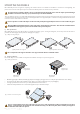
• The secure connection of connectors is identified by a firm click once inserted.
• The use of any chemicals or lubricants on the connectors or contacts must be carried out in line with the connector manufacturer’s instructions.
Any other modification to the panel is prohibited, including the opening of the junction box, unless explicitly authorized by REC.
Doing so will invalidate the warranty.
PROTECTING THE CABLES
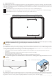
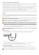
• To prevent stress on the junction box casing, ensure the cable exits the junction box in a straight line before any bend in the cable.
• The cables on REC TwinPeak panels have a minimum bending radius of mm to avoid damage to the insulation (fig. ).
• Ensure cables do not hang loose where they may be damaged through friction or stress, e.g., caused by wind or grazing animals.
• Shield connectors from falling or dropping water by locating them directly beneath a panel.
• Cables must be firmly secured to the structure, without over-tightening, as this can deform the cable insulation.
SECURING CABLES AND CONNECTORS
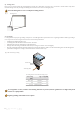
• When securing the connector, place it away from the mounting structure with sufficient air circulation all around. This allows the
connector to dry effectively and avoids the risk of damage or degradation of the connection.
• Good practice is to secure the cable either side of the connectors, ensuring no stress is exerted on the connector casing or cable entry.
To enable correct cooling and drying of the connectors, do not add extra protection to the connector, e.g., heat shrink, grease or tape.
< 60 mm >
< 30 mm >
Fig. : Minimum bend radius of mm and cable exiting the junction box