
Installation Guide

REC TwinPeak Installation Manual - IEC /
Rev E . Ref: NE
Grounding dimensions and wire fastening torque:
Cross section
[mm
2
]
Type Torque [Nm]
. . Stranded .
. Stranded .
. . Stranded / Solid .
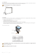
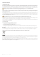
vii) Grounding
Local regulations may require grounding of the panels. Check all applicable requirements before beginning installation. Where grounding is
necessary, it must be done using an electrical connection from the panel frame:
• Suitable grounding lugs must be used.
• Grounding cable size should be between . mm
- . mm.
• Aach grounds to the grounding holes in the panel frames.
• Fix lug to the frame using a star washer and lock nut, ensuring a conductive connection (fig. ).
• Place the star washer between the frame and the nut, using a mm diameter stainless steel bolt and locking nut to mount the lug to the
panel frame and tighten according to the manufacturer’s recommended torque.
To avoid galvanic corrosion, stainless steel fastening materials are preferred, however galvanized or hot dipped zinc plated
fasteners are equally suitable.
Ensure the drainage holes are not covered by the mounting structure.
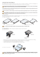
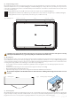
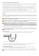
vi) Drainage holes
Each corner of the panel frame has small drainage holes (fig. ) to allow water caused by rain or snow melt to exit the frame easily and to
minimize damage caused by freezing and thawing. These must not be used for mounting the panel.
Fig. : Drainage holes
GR
GR
GR
GR
module back side
Grounding cable
Star washer
Fig.
: Recommended grounding
Negative grounding of the modules is not required.