
Installation Guide

REC TwinPeak Installation Manual - IEC /
Rev E . Ref: NE
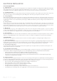
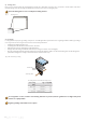
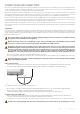
Minimum grip
length mm
Minimum grip
depth mm
Fig.
: Clamp specifications
MOUNTING THE PANELS
REC TwinPeak panels are designed for capturing solar radiation and are not suitable for installation as overhead or vertical glazing. The
junction box on the rear of the panel is protected to IP and allows panels to be mounted in any orientation.
The panels must be installed so that the cells are not shaded as this will drastically reduce electrical output. If partial shading is
inevitable at certain times of the day or year, it must be kept to an absolute minimum.
There are different options for securing an REC TwinPeak panel, depending on the design load of the array. Ensure the mounting structure design
can withstand anticipated wind and snow loads. Mounting hardware is not supplied by REC. Follow the mounting hardware manufacturer’s
instructions and recommendations at all times.
Ensuring sufficient airflow and adequate cooling of the panels can help improve performance. There must be a minimum distance
of 60 mm between the uppermost part of the roof and the lowest part of the panel.
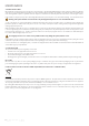
i) Rail specifications
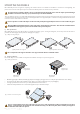
REC TwinPeak panels are typically installed on a rail-based mounting system. If using mounting rails, ensure they run under the frame or
parallel to the frame (fig ), directly under the clamping zones (fig ).
The overlap between the support rail and the outer edge of the frame must be a minimum of 6 mm.
ii) Clamp specification
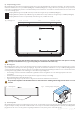
Ensure the clamps used are suitable for the planned installation and expected system design loads.
Fig. : Panels secured at four points.
Remove any labels or stickers that may be on the front of the panels (where applicable) and ensure no residue is le on the glass.
Fig. : Rail positioning examples:
(b) rails parallel to the short side
(a) rails parallel to the long side
Minimum grip
depth mm
Minimum grip
length mm
• Minimum grip length of mm, minimum grip depth of mm (fig. ). The grip must not overlap the panel frame and cause shading.
• The panel must be clamped by a minimum of two clamps per side (four clamping points per panel) (fig ).
• Use appropriate bolted connections as per clamp manufacturer’s instructions.
• Follow the clamp manufacturer’s recommended applied torque to fasten the clamps.
In areas of snow build-up panels can be subjected to forces in excess of the stated limit even when snow depth does not appear
extreme, causing damage to the framework. If the installation is likely to be affected by this, further suitable panel support is
recommended on the lower row of panels.
Rail positioning
Rail positioning
Rail positioning
Rail positioning