
Installation Guide


REC TwinPeak Installation Manual - IEC /
Rev E . Ref: NE
ANNEX . USE OF POWER OPTIMIZERS
Panels of the REC TwinPeak IQ Series only have been certified according to IEC / and UL for use with pre-installed
power optimizers. When installing REC TwinPeak IQ Series panels, care must be taken to ensure a safe and correct panel installation. When
installing REC TwinPeak IQ Series panels, follow the instructions below specific for such applications in addition to the above module mounting
instructions. Failure to do so may invalidate the warranty on the solar panel and/or the power optimizer.
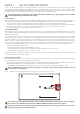
It is prohibited to make any modification to the mounting of the optimizer and the frame e.g., tightening the bolt, unless explicitly
authorized by REC. Doing so will invalidate the warranty.
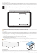
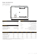
Fig. : Rail Exclusion Zone for REC TwinPeak IQ Series, showing position of the power optimizer on the frame
Ensure that no rails are installed in the Rail Exclusion Zone around the power optimizer as this may interfere with or damage the
power optimizer unit. The Rail Exclusion Zone measures 200 mm x 200 mm as marked in red in the above diagram.
GR
GR
GR
GR
200 mm
200 mm
Regularly check that the mechanical integrity of the optimizer mounted to the frame is intact (e.g., that there is no rust or corrosion
on the bolt assembly securing the optimizer in place).
PANEL HANDLING
Due to the addition of the power optimizer, REC TwinPeak IQ solar panels have different dimensions to them than standard panels and extra care
should be taken when handling and transporting them, including the following guidelines, in addition to those mentioned for standard panels.
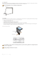
• Extra care must be taken if re-stacking panels aer initial unpacking due to the protruding optimizer from the rear.
• Panels must not be stacked horizontally as the aached power optimizer may be bent or broken if laid flat, or it may damage other hardware.
• Do not pull on the optimizer or any cables as this will damage the junction box, power optimizer and/or the bracket.
• Never apply any stickers or tape to any part of the power optimizer.
SAFETY REQUIREMENTS
When coupled to a power optimizer, the optimizer output is limited to V across the optimizer output terminal with the solar panel connected
to the optimizer. Treat the REC TwinPeak IQ Series panel and power optimizer with care, keeping in mind that the optimizer is a safety feature
that helps prevent accidents.
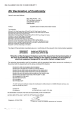
The power optimizer used on REC TwinPeak IQ Series solar panels has been tested and found to comply with the limits for a Class B digital
device, pursuant to part of the FCC Rules. These limits are designed to provide reasonable protection against harmful interference in a
residential installation. This equipment generates, uses and can radiate radio frequency energy and, if not installed and used in accordance
with the instructions, may cause harmful interference to radio communications. However, there is no guarantee that interference will not
occur in a particular installation. If this equipment does cause harmful interference to radio or television reception, which can be determined
by turning the equipment OFF and ON, you are encouraged to try to correct the interference by one or more of the following measures:
• Reorient or relocate the receiving antenna.
• Increase the separation between the equipment and the receiver.
• Connect the equipment to an outlet on a circuit different from that to which the receiver is connected.
• Consult the dealer or an experienced radio/TV technician for help.
Changes or modifications made to the solar panel or the power optimizer not expressly approved by the party responsible for compliance may
void the user’s authority to operate the equipment.
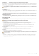
INSTALLATION RESTRICTIONS
When installing REC TwinPeak IQ series panels, the following instructions must be followed. For instructions on connecting the optimizer to
the solar module, please see the optimizer manufacturer’s instructions.
• Ensure that the Rail Exclusion Zone around the optimizer as shown in fig. is kept clear from rails or other parts of the mounting structure.
• Ensure that the drainage holes in the panel frame are not covered by any part of the mounting structure.
• Allow a minimum gap of mm around the optimizer in order to ensure free circulation of air and allowing effective cooling.
There is an additional hole on the center of the short side frame of the module. This hole must be kept free and is not to be used
for mounting or as a grounding point.