
User's Manual
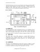
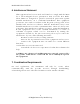
Table Of Contents

Realtek DWA User Guide.doc
The RF performance can also be tested using the test utility provided by NEC.
Two basic clock frequencies are used in the system – 30MHz for MAC and
66MHz for PHY. Some more details of the components are shown in the
following sections. The system block diagram is shown below.
Figure 1 System Block Diagram
2.1. UWB PHY
This chip integrates the RF and baseband functions of a UWB PHY defined
by the standard. This version of PHY chip is packaged in 48-pin QFN form
factor. The analog/RF section requires 1.8V and 3.3V to operate. The digital
core operates with 1.5V and the I/O voltage can support a range of 1.8V~3.3V.
2.2. NEC MAC
This MAC chip is from NEC which has a standard MPI interface to
communicate with a standard UWB PHY, as well as a high speed USB
interface(the upstream port) to connect directly to a PC. This chip requires
voltages of 1.5V and 3.3V.
2.3. EEPROM
This chip is a serial EEPROM from Atmel with a capacity of 256Kb. It is used
by the MAC to store the initialization data and command sequence required
by the MAC and PHY on start up. This chip requires 3.3V only.
4
All Rights Reserved by Realtek Corp.