
User's Manual
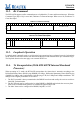
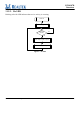
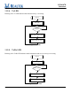
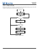
Table Of Contents
- RTL8187B_DataSheet_1.022.pdf
- RTL8187B_DataSheet_1.022.pdf
- RTL8187B_DataSheet_1.022.pdf
- General Description
- Features
- System Applications
- Block Diagram
- Pin Assignments
- Pin Descriptions
- CPU Access to Endpoint Data
- USB Request
- Get Descriptor-Device
- Get Descriptor-Device Qualifier (High Speed)
- Get Descriptor-Configuration
- Get Descriptor-String Index 0
- Get Descriptor-String Index 1
- Get Descriptor-String Index 2
- Get Descriptor-String Index 3
- Get Descriptor-String Index 4
- Get Descriptor-String Index 5
- Get Descriptor-Other Speed Configuration
- Set Address
- Set Interface 0
- Set Feature Device
- Clear Feature Device
- Set Config 0
- Set Config 1
- EEPROM (93C46 or 93C56) Contents
- USB Packet Buffering
- Functional Description
- Application Diagram
- Electrical Characteristics
- Mechanical Dimensions
- Ordering Information
- SGS Test Report
- RTL8187L manual1.pdf
- RTL8187B_DataSheet_1.022.pdf
- RTL8187B_DataSheet_1.022.pdf

RTL8187B
Datasheet
Wireless LAN Network Interface Controller
31
Track ID: JATR-1076-21 Rev. 1.0
11.8.
Duration Field Processing
The RTL8187B supports three modes of duration field processing (selected via the DurProcMode bit in
each AC_XX_TXOPQueued register).
• Mode 0: Software takes full control of duration field processing. MAC has nothing to do with it.
• Mode 1: DMA reads the 2-byte DURATION value in the TX descriptor and adds it to the
AC_XX_TXOPQueued register.
• Mode2: Hardware accumulates all the requested duration values of each EDCAF data queue and each
EDCAF FIFO and writes the value to each corresponding AC_XX_TXOPQueued register.
In Mode1 and Mode2, MAC decreases the value in the AC_XX_TXOPQueued register each time an
EDCAF packet is transmitted.
11.9.
LED Functions
The RTL8187B supports 2 LED signals in 4 configurable operation modes. The following sections describe
the different LED actions.
11.9.1. Link Monitor
The Link Monitor senses the link integrity. Whenever link status is established, the specific link LED pin is
driven low.
11.9.2. Infrastructure Monitor
The Infrastructure Monitor senses the link integrity of an Infrastructure network. Whenever Link OK in
Infrastructure network status is established, the specific Infrastructure LED pin is driven low.