
User's Manual
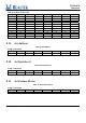
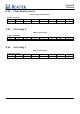
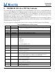
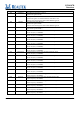
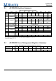
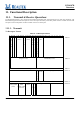
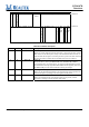
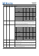
Table Of Contents
- RTL8187B_DataSheet_1.022.pdf
- RTL8187B_DataSheet_1.022.pdf
- RTL8187B_DataSheet_1.022.pdf
- General Description
- Features
- System Applications
- Block Diagram
- Pin Assignments
- Pin Descriptions
- CPU Access to Endpoint Data
- USB Request
- Get Descriptor-Device
- Get Descriptor-Device Qualifier (High Speed)
- Get Descriptor-Configuration
- Get Descriptor-String Index 0
- Get Descriptor-String Index 1
- Get Descriptor-String Index 2
- Get Descriptor-String Index 3
- Get Descriptor-String Index 4
- Get Descriptor-String Index 5
- Get Descriptor-Other Speed Configuration
- Set Address
- Set Interface 0
- Set Feature Device
- Clear Feature Device
- Set Config 0
- Set Config 1
- EEPROM (93C46 or 93C56) Contents
- USB Packet Buffering
- Functional Description
- Application Diagram
- Electrical Characteristics
- Mechanical Dimensions
- Ordering Information
- SGS Test Report
- RTL8187L manual1.pdf
- RTL8187B_DataSheet_1.022.pdf
- RTL8187B_DataSheet_1.022.pdf

RTL8187B
Datasheet
Wireless LAN Network Interface Controller
18
Track ID: JATR-1076-21 Rev. 1.0
9. EEPROM (93C46 or 93C56) Contents
The RTL8187B supports the attachment of an external EEPROM. The 93C46 is a 1Kbit EEPROM (the
93C56 is a 2Kbit EEPROM). The EEPROM interface provides the ability for the RTL8187B to read from,
and write data to, an external serial EEPROM device. If the EEPROM is not present, the RTL8187B
initialization uses default values for the Operational Registers. Software can read and write to the
EEPROM using “bit-bang” accesses via the 9346CR Register.
Although it is actually addressed by words, its contents are listed below by bytes for convenience. After the
initial power on or auto-load command in the 9346CR, the RTL8187B performs a series of EEPROM read
operations from the 93C46 (93C56).
Note: It is suggested to obtain Realtek approval before changing the default settings of the EEPROM.
Table 24. EEPROM (93C46 or 93C56) Contents
Bytes Contents Description
00h 29h
01h 81h
These 2 bytes contain the ID code word for the RTL8187B. The RTL8187B will load
the contents of the EEPROM into the corresponding location if the ID word (8129h) is
correct.
02h-03h VID USB Vendor ID.
04h-05h DID USB Device ID.
06h ChannelPlan Channel Plan: Map of channels to be scanned.
07h Reserved -
08h Reserved -
09h Version Bit [7:6] Interface Selection
00 : USB
01 : Mini Card
02 : Reserved
03 : Reserved
Bit [5:0] The EEPROM version.
0Ah Tx Power Base Tx power of the serving base station.
0Bh Reserved -
0Ch RFChipID RF Chip ID.
The identifier of the RF chip.
0Dh CONFIG3 RTL8187B Configuration register 3.
Operational register FF59h.
0Eh~13h MAC Address MAC Address.
After the auto-load command or a hardware reset, the RTL8187B loads MAC
Addresses to IDR0~IDR5 of the I/O registers of the RTL8187B.
14h TxPower12 Transmit Power Level for 802.11b(g)-defined channel_ID 12
(center frequency=2467MHz).
15h CONFIG1 RTL8187B Configuration register 1.
Operational register FF52h.
Bit[5:2] : USB receive sensitivity
16h~17h
CRC 16-bit CRC value of EEPROM content. Reserved for Software use.
18h CONFIG2 RTL8187B Configuration register 2.
Operational register FF53h.