RTL8187B-GR WIRELESS LAN NETWORK INTERFACE CONTROLLER DATASHEET Rev. 1.0 09 October 2006 Track ID: JATR-1076-21 Realtek Semiconductor Corp. No. 2, Innovation Road II, Hsinchu Science Park, Hsinchu 300, Taiwan Tel.: +886-3-578-0211. Fax: +886-3-577-6047 www.realtek.com.
RTL8187B Datasheet COPYRIGHT ©2006 Realtek Semiconductor Corp. All rights reserved. No part of this document may be reproduced, transmitted, transcribed, stored in a retrieval system, or translated into any language in any form or by any means without the written permission of Realtek Semiconductor Corp. DISCLAIMER Realtek provides this document “as is”, without warranty of any kind, neither expressed nor implied, including, but not limited to, the particular purpose.
RTL8187B Datasheet Table of Contents 1. GENERAL DESCRIPTION ...............................................................................................................................................1 2. FEATURES ..........................................................................................................................................................................2 3. SYSTEM APPLICATIONS ..............................................................................................
RTL8187B Datasheet 10.3. 11. PACKET RECOGNITION ..............................................................................................................................................22 FUNCTIONAL DESCRIPTION ..................................................................................................................................23 11.1. TRANSMIT & RECEIVE OPERATIONS..........................................................................................................................
RTL8187B Datasheet TABLE 16. GET DESCRIPTOR-STRING INDEX 5 ..............................................................................................................................15 TABLE 17. GET DESCRIPTOR-OTHER SPEED CONFIGURATION ......................................................................................................15 TABLE 18. SET ADDRESS ..................................................................................................................................................
RTL8187B Datasheet 1. General Description The Realtek RTL8187B is a low-profile highly integrated cost-effective Wireless LAN USB 2.0 network interface controller that integrates a USB 2.0 PHY, SIE (Serial Interface Engine), 8051 MCU, a Wireless LAN MAC, and a Direct Sequence Spread Spectrum/OFDM baseband processor onto one chip. It provides USB high speed (480Mbps), and full speed (12Mbps), and supports 9 endpoints for transfer pipes.
RTL8187B Datasheet 2. Features 128-Pin LQFP with ‘Green’ package OFDM with BPSK, QPSK, 16QAM and 64QAM modulations and demodulations supported with rate compatible punctured convolutional coding with coding rate of 1/2, 2/3, and 3/4 State machine implementation without external memory (RAM, flash) requirement Complies with IEEE 802.
RTL8187B Datasheet Uses 93C46 (64*16-bit EEPROM) or 93C56 (128*16-bit EEPROM) to store resource configuration and ID parameter data Embedded standard 8051 CPU with enhanced features: Four cycles per instruction LED pins for various network activity indications Variable clock speed cuts power consumption Six GPIO pins supported Supports 9 endpoints: 64-Byte buffer for control endpoint Supports digital loopback capability on both ports Two 512-Byte buffers for bulk IN endpoint Scatter and gather opera
RTL8187B Datasheet 4.
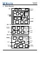
RTL8187B Datasheet 5. Pin Assignments Figure 2. Pin Assignments 5.1. Green Package and Version Identification Green package is indicated by a ‘G’ in the location marked ‘T’ in Figure 2. Wireless LAN Network Interface Controller 5 Track ID: JATR-1076-21 Rev. 1.
RTL8187B Datasheet 6. Pin Descriptions In order to reduce pin count, and therefore size and cost, some pins have multiple functions. In such cases, the functions are separated with a ‘/’ symbol. Refer to the Pin Assignments diagram on page 5 for a graphical representation. The following signal type codes are used in the tables: I: Input. S/T/S: Sustained Tri-State. O: Output O/D: Open Drain. T/S: Tri-State bi-directional input/output pin. 6.1. USB Transceiver Interface Table 1.
RTL8187B Datasheet 6.4. LED Interface Table 4. LED Interface Symbol LED0, 1 Type O Pin No 48, 56 Description LED Pins (Active low) LEDS1~0 00 01 10 11 LED0 TX/RX TX/RX TX LINK/ACT LED1 Infrastructure LINK RX Infrastructure During power down mode, the LED signals are logic high. 6.5. Attachment Unit Interface 6.5.1. RTL8225 RF Chipset Table 5.
RTL8187B Datasheet Symbol GPIO4 GPIO5 VREFO VRP VRN RXIP RXIN RXQP RXQN RXAGC TXAGC RSSI TSSI0 TSSI1 TXQP TXQN TXIP TXIN TXQTP TXQTN TXITP TXITN 6.5.2. Type O O X X X I I I I I O I I I I I O O O O O O Pin No 100 94 118 119 120 121 122 124 125 4 5 6 7 8 11 12 14 13 15 16 17 18 Description General purpose input/output pin. General purpose input/output pin. Not used in the RTL8225 RF chipset. Not used in the RTL8225 RF chipset. Not used in the RTL8225 RF chipset. Receive (Rx) In-phase Analog Data.
RTL8187B Datasheet Symbol RFTXEN RFRXEN GPIO[0] GPIO[1] GPIO[2] GPIO[3] GPIO[4] GPIO[5] VREFO VRP VRN RXIP RXIN RXQP RXQN RXAGC TXAGC RSSI TSSI0 TSSI1 TXQP TXQN TXIP TXIN TXQTP TXQTN TXITP TXITN 6.6. Type O O O O O O O O X X X I I I I O O I I I O O O O O O O O Pin No 102 113 67 68 69 70 100 94 118 119 120 121 122 124 125 4 5 6 7 8 11 12 14 13 15 16 17 18 Description Not used in the RTL8255 RF chipset. Not used in the RTL8255 RF chipset. General purpose input/output pin. General purpose input/output pin.
RTL8187B Datasheet 7. CPU Access to Endpoint Data 7.1. Control Transfer Control transfers configure and send commands to a device. Because they are so important, they employ extensive USB error checking. The host reserves a portion of each USB frame for control transfers. Control transfers consist of two or three stages. The SETUP stage contains eight bytes of USB control data. An optional DATA stage contains more data, if required.
RTL8187B Datasheet 8. USB Request 8.1. Get Descriptor-Device Table 8. Get Descriptor-Device Setup Transaction BmReq 80 bReq 06 wValueL 00 wValueH 01 wIndexL 00 wIndexH 00 wLengthL Lengh_L wLengthH Length_H DATA3 02 81 DATA4 00 00 DATA5 00 01 DATA6 00 01 DATA7 40 02 DATA3 01 81 DATA4 00 00 DATA5 00 01 DATA6 00 01 DATA7 40 02 High Speed Data Transaction DATA0 12 DA 03 DATA1 01 0B 01 DATA2 00 87 Full Speed Data Transaction DATA0 12 DA 03 8.2.
RTL8187B Datasheet 8.3. Get Descriptor-Configuration Table 10.
RTL8187B Datasheet 8.4. Get Descriptor-String Index 0 Table 11. Get Descriptor-String Index 0 Setup Transaction BmReq 80 bReq 06 wValueL 00 wValueH 03 wIndexL 00 wIndexH 00 wLengthL Lengh_L DATA2 09 DATA3 04 DATA4 - DATA5 - DATA6 - wLengthH Length_H Data Transaction DATA0 04 8.5. DATA1 03 DATA7 - Get Descriptor-String Index 1 Table 12.
RTL8187B Datasheet 8.7. Get Descriptor-String Index 3 Table 14. Get Descriptor-String Index 3 Setup Transaction BmReq 80 bReq 06 wValueL 03 wValueH 03 wIndexL 09 wIndexH 04 wLengthL Lengh_L DATA2 30 34 30 DATA3 00 00 00 DATA4 30 63 30 DATA5 00 00 00 DATA6 65 30 30 wLengthH Length_H Data Transaction DATA0 1A 30 30 31 8.8. DATA1 03 00 00 00 DATA7 00 00 00 Get Descriptor-String Index 4 Table 15.
RTL8187B Datasheet 8.9. Get Descriptor-String Index 5 Table 16. Get Descriptor-String Index 5 Setup Transaction BmReq 80 bReq 06 wValueL 05 wValueH 03 wIndexL 09 wIndexH 04 wLengthL Lengh_L DATA2 55 48 65 6C 6E 74 DATA3 00 00 00 00 00 00 DATA4 53 53 72 20 76 65 DATA5 00 00 00 00 00 00 DATA6 42 20 69 43 65 72 wLengthH Length_H Data Transaction DATA0 30 20 48 61 6F 72 8.10. DATA1 03 00 00 00 00 00 DATA7 00 00 00 00 00 00 Get Descriptor-Other Speed Configuration Table 17.
RTL8187B Datasheet Full Speed Data Transaction DATA0 09 FA FF 00 07 05 07 02 40 00 00 8.11. DATA1 07 09 02 07 05 06 02 40 00 00 DATA2 51 04 07 05 05 02 40 00 00 07 DATA3 00 00 05 04 02 40 00 00 07 05 DATA4 01 00 83 02 40 00 00 07 05 0C DATA5 01 09 02 40 00 00 07 05 0B 02 DATA6 04 FF 40 00 00 07 05 0A 02 40 DATA7 80 FF 00 00 07 05 89 02 40 00 wIndexH 00 wLengthL 00 wLengthH 00 wIndexH 00 wLengthL 00 wLengthH 00 wIndexH 00 wLengthL 00 wLengthH 00 Set Address Table 18.
RTL8187B Datasheet 8.14. Clear Feature Device Table 21. Clear Feature Device Setup Transaction BmReq bReq 00 01 Note: No data transaction. 8.15. wValueL 01 wValueH 00 wIndexL 00 wIndexH 00 wLengthL 00 wLengthH 00 wIndexH 00 wLengthL 00 wLengthH 00 wIndexH 00 wLengthL 00 wLengthH 00 Set Config 0 Table 22. Set Config 0 Setup Transaction BmReq bReq 00 09 Note: No data transaction. 8.16. wValueL 00 wValueH 02 wIndexL 00 Set Config 1 Table 23.
RTL8187B Datasheet 9. EEPROM (93C46 or 93C56) Contents The RTL8187B supports the attachment of an external EEPROM. The 93C46 is a 1Kbit EEPROM (the 93C56 is a 2Kbit EEPROM). The EEPROM interface provides the ability for the RTL8187B to read from, and write data to, an external serial EEPROM device. If the EEPROM is not present, the RTL8187B initialization uses default values for the Operational Registers. Software can read and write to the EEPROM using “bit-bang” accesses via the 9346CR Register.
RTL8187B Datasheet Bytes 19h Contents CONFIG4 1Ah~1Dh ANA_PARM 1Eh TESTR 1Fh CONFIG5 20h TxPower36 21h TxPower40 22h TxPower44 23h TxPower48 24h TxPower52 25h TxPower56 26h TxPower60 27h TxPower64 28h TxPower149 29h TxPower153 2Ah TxPower157 2Bh TxPower161 2Ch TxPower1 2Dh TxPower2 2Eh TxPower3 2Fh TxPower4 30h TxPower5 31h TxPower6 Description RTL8187B Configuration register 4. Operational register FF5Ah. Analog Parameter for the RTL8187B.
RTL8187B Datasheet Bytes 32h-35h 36h 37h Contents ANA_PARM2 Description Analog Parameter 2 for RTL8187B. Operational registers for the RTL8187B are 60h to 63h. Reserved. Do not change this field without Realtek approval. TxPower11 Transmit Power Level for 802.11b(g)-defined channel_ID 11 (center frequency=2462MHz). Optional functions Bit[1:0]: Suspend pin behavior. 00b: Default pull high 01b: Default pill low 10b: Functions as a PME# signal Bit[2]: USB remote wake up function.
RTL8187B Datasheet 9.1. EEPROM Registers Summary Table 25.
RTL8187B Datasheet 10. USB Packet Buffering The RTL8187B incorporates two independent FIFOs for transferring data to/from the system interface and from/to the network. The FIFOs provide temporary storage of data, freeing the host system from the real-time demands of the network. The way in which the FIFOs are emptied and filled is controlled by the FIFO threshold values in the Receive Configuration registers. These values determine how full or empty the FIFOs must be before the device requests the bus.
RTL8187B Datasheet 11. Functional Description 11.1. Transmit & Receive Operations The RTL8187B supports a new descriptor-based buffer management that will significantly lower host CPU utilization. The RTL8187B supports transmit descriptor and receive descriptor in memory. Each OUT packet contains 3-double-word transmit descriptors and each IN packet contains 4-double-word receive descriptors. 11.1.1. Transmit Tx Descriptor Format Table 27.
RTL8187B Datasheet 31 30 29 28 27 26 25 24 23 R SPC A S N V T D E N N A 22 21 20 19 18 17 16 15 14 13 12 11 10 AGC (8 bits) FRAG_QSIZE (16 bits) RSVD (4bits) 9 8 7 6 5 4 3 2 1 0 DELAY_BOUND (16 bits) E N _ P M P D E BCKEY (6 bits) N _ B C K E Y P T _ E N T P C _ E N TPC _PO LAR ITY T P C _ D E S E N Offset 24 R S V D HW Leng thSel ect Offset 28 Table 28.
RTL8187B Datasheet Offset# 0 Bit# 27:24 Symbol TXRATE 0 23 RTSEN 0 22:19 RTSRATE 0 18 CTSEN 0 17 MOREFRAG 0 16 SPLCP Wireless LAN Network Interface Controller Description Tx Rate. These five bits indicate the current frame’s transmission rate. Bit 27 Bit 26 Bit 25 Bit 24 1Mbps 0 0 0 0 2Mbps 0 0 0 1 5.5Mbps 0 0 1 0 11Mbps 0 0 1 1 6Mbps 0 1 0 0 9Mbps 0 1 0 1 12Mbps 0 1 1 0 18Mbps 0 1 1 1 24Mbps 1 0 0 0 36Mbps 1 0 0 1 48Mbps 1 0 1 0 54Mbps 1 0 1 1 Reserved All other combinations RTS Enable.
RTL8187B Datasheet Offset# 0 Bit# 15 Symbol NO_ENCRYPT 0 14:12 RSVD 0 11:0 TPKTSIZE 4 31 LENGEXT 4 30:16 Length 4 15:0 RTSDUR 8 12 12 12 12 31:0 31:16 15 14:12 11:0 TxBuff DURATION MIC_CAL RSVD Frame_Length 16 31:0 NTDA 20 31:27 20 26:23 20 22:19 20 18 PIFS 20 17 NO_ACM 20 16 RT_DB 20 15:8 RETRY_LIMIT 20 7:0 RTSAGC 24 31 RSVD 24 30:29 SPC 24 28 ANTENNA 24 27:20 AGC Tx AGC. 24 19:16 RSVD Reserved.
RTL8187B Datasheet Offset# 28 Bit# 31:16 Symbol FRAG_QSIZE 28 15 ENPMPD 28 14 EN_BCKEY 28 13:8 BCKEY Specify key to use in CAM for broadcast/multicast. 28 7 PT_EN Enable Power Tracking. 28 6 TPC_EN 28 5:4 TPC_POLARITY 28 3 TPC_DESEN 28 1:0 HWLengthSelect Description Fragmentation Queue Size. Upon sending the first frame of a fragmentation sequence, the driver writes the queue size of the entire fragmentation exchange (including the first frame) here.
RTL8187B Datasheet Table 30. Rx Status Descriptor Offset# 0 Bit# 31 Symbol OWN Description Ownership. When set, this bit indicates that the descriptor is owned by the NIC. When clear, it indicates that the descriptor is owned by the host system. The NIC clears this bit when the related buffer data has been transmitted. In this case, OWN=0. DMA Okay. 0 30 DMA_OK 0 29 FS 0 28 LS 0 27:17 RSVD First Segment Descriptor.
RTL8187B Datasheet 11.2. Rx Command The RTL8187B supports an Rx command queue to feedback the Tx state and beacon interrupt . When the Command Type (bit[31:30]) is set to 00b, it indicates Tx Beacon Interrupt. When set to 01b, it indicates Tx Close Descriptor. Table 31. Tx Beacon Interrupt 31 30 29 28 27 26 25 24 23 22 21 20 19 18 17 16 15 14 13 12 11 10 9 Cmd 8 7 RSVD 6 5 4 3 2 1 0 2 1 0 Last Beacon CW Type Last Beacon TSF[31:0] Table 32.
RTL8187B Datasheet 11.5. Rx Decapsulation (With RTL8187B Internal Baseband Processor) The RTL8187B continuously monitors the network when reception is enabled. When activity is recognized it starts to process the incoming data. After detecting receive activity on the channel, the RTL8187B starts to process the PLCP preamble and header based on the mode of operation. The RTL8187B checks CRC16 and CRC32, then reports if CRC16 or CRC32 has errors.
RTL8187B Datasheet 11.8. Duration Field Processing The RTL8187B supports three modes of duration field processing (selected via the DurProcMode bit in each AC_XX_TXOPQueued register). • Mode 0: Software takes full control of duration field processing. MAC has nothing to do with it. • Mode 1: DMA reads the 2-byte DURATION value in the TX descriptor and adds it to the AC_XX_TXOPQueued register.
RTL8187B Datasheet 11.9.3. Rx LED Blinking of the Rx LED indicates that receive activity is occurring. Power On LED = High Receiving Packet? No Yes LED = High for (100 +- 10) ms LED = Low for (12 +- 2) ms Figure 3. Rx LED Wireless LAN Network Interface Controller 32 Track ID: JATR-1076-21 Rev. 1.
RTL8187B Datasheet 11.9.4. Tx LED Blinking of the Tx LED indicates that transmit activity is occurring. Power On LED = High Transmitting Packet? No Yes LED = High for (100 +- 10) ms LED = Low for (12 +- 2) ms Figure 4. Tx LED 11.9.5. Tx/Rx LED Blinking of the Tx/Rx LED indicates that both transmit and receive activity is occurring. Power On LED = High Tx/Rx Packet? No Yes LED = High for (100 +- 10) ms LED = Low for (12 +- 2) ms Figure 5.
RTL8187B Datasheet 11.9.6. LINK/ACT LED Blinking of the LINK/ACT LED indicates that the RTL8187B is linked and operating properly. If this LED is high for extended periods it indicates that a link problem exists. Power On LED = High No Link? Yes LED = Low No Tx/Rx packet? Yes LED = High for (100 +- 10) ms LED = Low for (12 +- 2) ms Figure 6. LINK/ACT LED Wireless LAN Network Interface Controller 34 Track ID: JATR-1076-21 Rev. 1.
RTL8187B Datasheet 12. Application Diagram Main/Aux. Power Regulators Power 3.3V, 1.5V LED External ROM/RAM Power 3.3V, 1.5V Power 3.3V, 1.8V RTL8187B Antenna External RF Devices D+ Base Band 40MHz Clock MAC SIE EEPROM D- Power 3.3V Figure 7. Application Diagram Wireless LAN Network Interface Controller 35 Track ID: JATR-1076-21 Rev. 1.
RTL8187B Datasheet 13. Electrical Characteristics 13.1. Temperature Limit Ratings Table 33. Temperature Limit Ratings Parameter Storage temperature Operating temperature 13.2. Minimum -55 -10 Maximum +125 70 Units °C °C DC Characteristics Table 34. DC Characteristics Symbol Parameter VDD33 VDD15 Conditions Minimum Typical Maximum Units 3.3V Supply Voltage 3.0 3.3 3.6 V 1.5V Supply Voltage 1.4 1.5 1.6 V Vcc V 0.
RTL8187B Datasheet 13.3. AC Characteristics 13.3.1. Serial EEPROM Interface Timing (93C46(64*16)/93C56(128*16)) EESK tcs EECS EEDI (Read) 1 1 0 An A2 A1 A0 (Read) 0 EEDO High Impedance Dn D1 D0 EESK tcs EECS EEDI (Write) 1 0 1 An ... A0 Dn ... D0 (Write) BUSY EEDO High Impedance READY twp tsk EESK tskh tcss tdis EECS tcsh tskl tdih EEDI tdos tdoh EEDO (Read) tsv EEDO STATUS VALID (Program) Figure 8. Serial EEPROM Interface Timing Table 35.
RTL8187B Datasheet 14. Mechanical Dimensions See the Mechanical Dimensions notes on the next page. Wireless LAN Network Interface Controller 38 Track ID: JATR-1076-21 Rev. 1.
RTL8187B Datasheet 14.1. Symbol A A1 A2 b c D D1 e E E1 L L1 Θ Mechanical Dimensions Notes Dimension in inch Min Typical Max 0.063 0.002 0.053 0.055 0.057 0.005 0.007 0.009 0.004 0.006 0.624 0.630 0.636 0.547 0.551 0.555 0.016 BSC 0.624 0.630 0.636 0.547 0.551 0.555 0.018 0.024 0.030 0.039 REF 0° 3.5° 7° Dimension in Min Typical 0.05 1.35 1.40 0.13 0.18 0.09 15.85 16.00 13.90 14.00 0.40 BSC 15.85 16.00 13.90 14.00 0.45 0.60 1.00 REF 0° 3.5° mm Max 1.60 1.45 0.23 0.20 16.15 14.10 16.15 14.10 0.
Test Report REALTEK SEMICONDUCTOR CORP. Report No. : CE/2005/12075 NO. 2, INDUSTRY E. RD.
Test Report REALTEK SEMICONDUCTOR CORP. Report No. : CE/2005/12075 NO. 2, INDUSTRY E. RD. IX, SCIENCE-BASED INDUSTRIAL Date : 2005/01/20 PARK, HSINCHU 300, TAIWAN Page : 2 of 2 Test Result : PART NAME NO.1 MIXED BLACK PLASTIC BODY&SILVER COLORED METAL-MIXED ALL PART Test Item (s): Unit Method MDL PBBs(Polybrominated biphenyls)(CAS NO:05953665-1) % 0.0005 PBBEs(PBDEs)(Polybrominat ed biphenyl ethers) % With reference to USEPA3540 or USEPA3550. Analysis was performed by HPLC/DAD, LC/MS or GC/MS.
Federal Communication Commission Interference Statement This equipment has been tested and found to comply with the limits for a Class B digital device, pursuant to Part 15 of the FCC Rules. These limits are designed to provide reasonable protection against harmful interference in a residential installation. This equipment generates, uses and can radiate radio frequency energy and, if not installed and used in accordance with the instructions, may cause harmful interference to radio communications.
20cm minimum distance has to be able to be maintained between the antenna and the users for the host this module is integrated into. Under such configuration, the FCC radiation exposure limits set forth for an population/uncontrolled environment can be satisfied. Any changes or modifications not expressly approved by the manufacturer could void the user's authority to operate this equipment.
IC Radiation Exposure Statement: "Operation is subject to the following two conditions: (1) this device may not cause interference, and (2) this device must accept any interference, including interference that may cause undesired operation of the device." Without Co-located The antenna (s) used for this transmitter must not be co-located or operating in conjunction with any other antenna or transmitter. For product available in the USA/Canada market, only channel 1~11 can be operated.