
Specifications
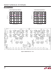
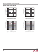
Table Of Contents
9
dc2064af
DEMO MANUAL DC2064A
QUICK START PROCEDURE
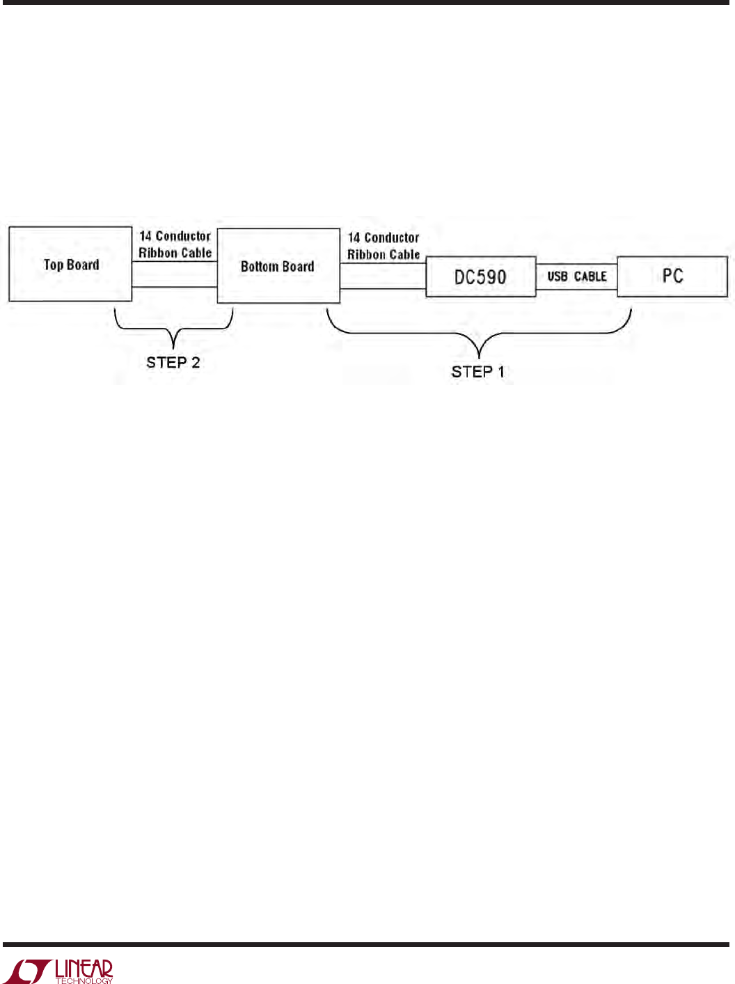
Tw o Board Setup and Operation:
As a result of communication latency to the PC, the system
only supports two series DC2064A boards
When connecting two DC2064A boards together, the in-
terface cables must be connected in sequence as shown
in Figure 20 to avoid large inrush currents. The DC590B
must be connected to the PC USB port and the
bottom
DC2064A board first and then the top DC2064A board
may be connected.
The 24 cells should be interconnected to allow balancing
between the two 12-cell stacks, as shown in Figure 21.
Figure 20. Tw o DC2064A SPI Connection Sequence
DC2064A DC2064A