
Specifications

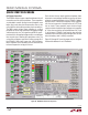
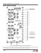
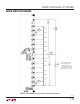


Table Of Contents
12
dc2064af
DEMO MANUAL DC2064A
QUICK START PROCEDURE
Cell Bypass Capacitors
The DC2064 contains bypass capacitors between the cell
connections and the stack connections. These capacitors
are intended to smooth the high current triangular wave
before they travel down the interconnection wires to the
cells within the stack and the secondary stack connections.
The RMS current rating of these capacitors is a critical
parameter as well as their capacitance
with applied voltage
and their physical size. The capacitance of MLCC capaci-
tors decreases with applied voltage and this must be taken
into account when selecting the capacitance value. The
value of the cell bypass capacitor is outline on page 31 of
the LTC3300-1 data sheet. Larger size, 1812 and above,
MLCC capacitors have a tendency to crack and short due
to thermal expansion and physical stress.
Each cell
must have an equal capacitance between them
to prevent an overvoltage condition across the cell when
randomly connecting batteries to the LTC3300-1 battery
balancer circuit. There are also capacitors across adjacent
cells that act a reservoir of charge for the cell’s FET Gate
turn on circuit. These capacitors must also be of equal
value to maintain the balancing of voltage and a capacitor
of ½ the
value need to be connected between Cell 1 and
V– of the lowest LTC3300-1 and from the top cell to the
cell below it to ensure balancing of voltage across all cells
when the battery stack is initially connected.
Figure 29 through 35 show the proper way to configure
the board for between 4 and 11 batteries.
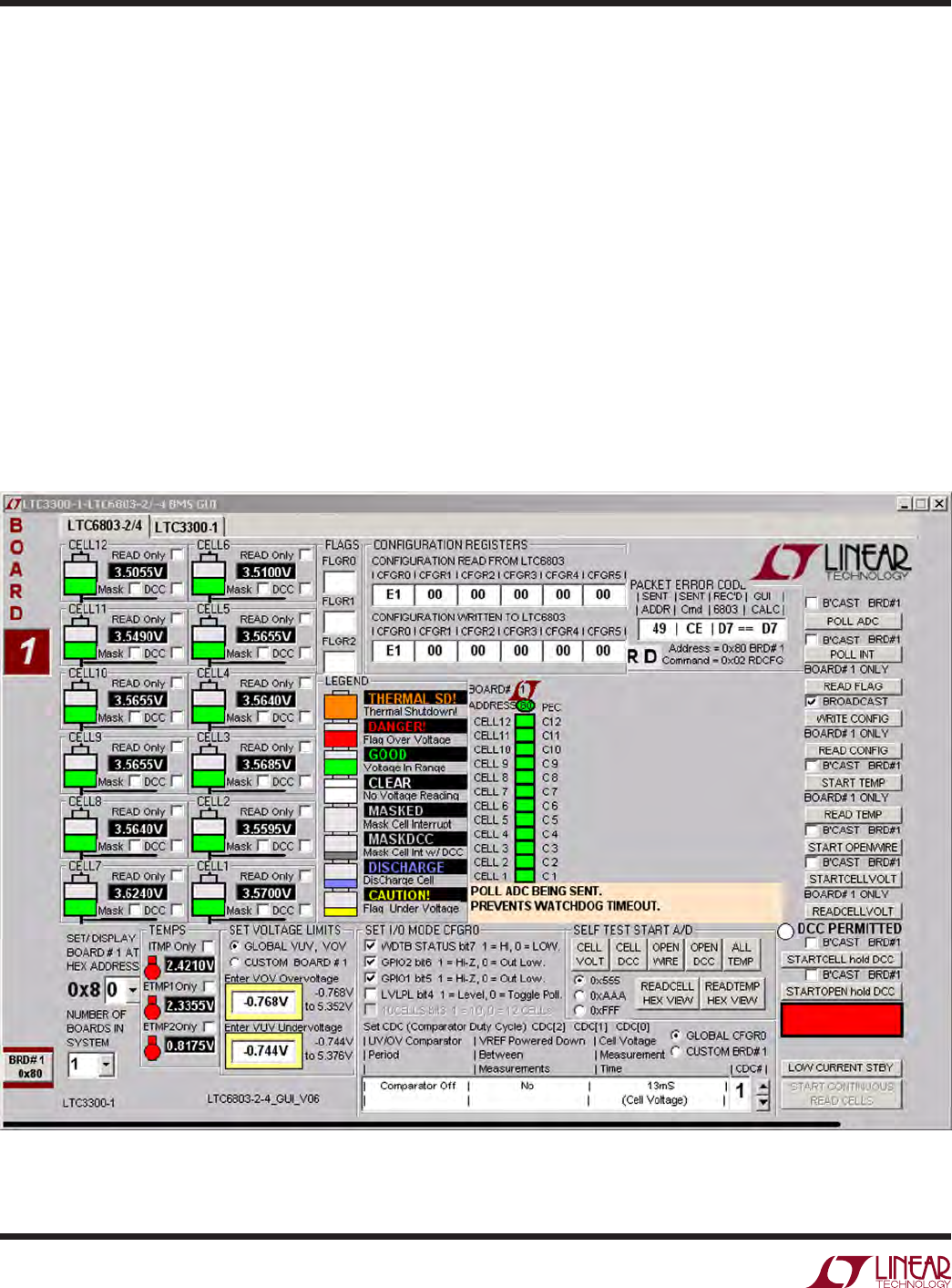
Figure 24. DC2064A LTC6803-2 Setup Screen