
Specifications

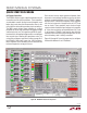
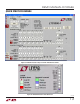
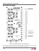
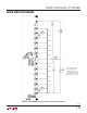


Table Of Contents
11
dc2064af
DEMO MANUAL DC2064A
QUICK START PROCEDURE
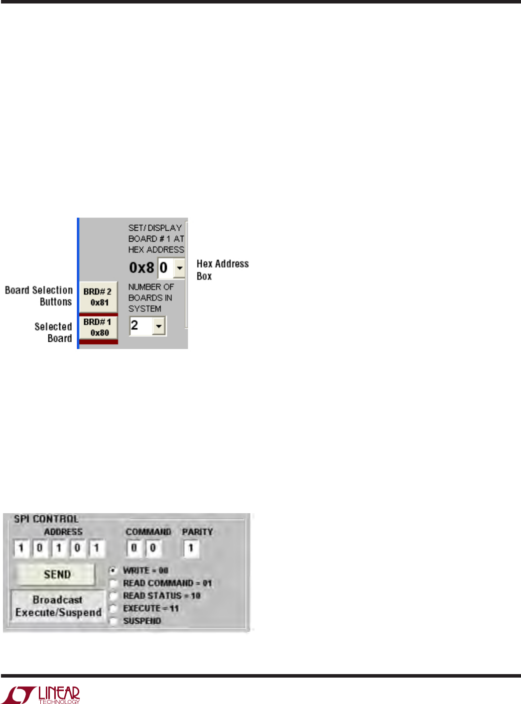
On the LTC6803-2 tab on the DC2064A GUI, the Number
of Boards in the System drop down box will need to be
changed to 2. Make sure the address for each board in
the Hex Address box matches the address set by the A0
to A3 jumpers on the respective DC2064A board. The
board selection buttons on the bottom left
side of the GUI
highlight which board is selected in maroon, as shown
and the set hexadecimal address is displayed under each
board. To change the hexadecimal address on the GUI,
select the board to change by clicking on the appropriate
board selection number and then select the correct ad-
dress in the Hex Address Box.
Figure 22. DC2064A GUI Board Selection Controls
To set up the charge and discharge actions for each
LTC3300, the appropriate board must be selected first and
then the commands for each LTC3300-1 can be selected
and written to the LTC3300-1 tab. When all the desired
actions are selected and written to the four LTC3300-1
ICs, then a single execute command will send an execute
command to both boards simultaneously provided the
Broadcast Execute/Suspend button is
selected as shown
in Figure 23.
Figure 23. Broadcast Execute/Suspend Tab
Additional Circuitry
Additional circuitry has been added to increase the ro-
bustness of the design for fault insertions.
Cell 6 Wire Disconnection
A 10A 200V Schottky diode has been added for a high
current path when the connection between battery cells
is broken when a battery stack load is present. The 200V
reverse voltage rating of the diode was selected to mini-mize
the reverse
leakage current at a battery voltage of 4.2V.
The 10A current rating was selected for its low forward
voltage drop which will minimize the current in the parallel
diode within the LTC3300-1 as well as surviving the fusing
current of the 7A fuses on the DC2064A.
Tw o overvoltage detection circuits have been added to the
design that will sense an overvoltage condition on Cell 6
and
Cell 7 when a disconnection of the Cell 6 wire con-
nection between battery Cell 6+ and battery Cell 7– of the
battery stack occurs. When Cell 6 is being discharged and
other cells controlled by the U1, the lower LTC3300-1, and
U2, the upper LTC3300-1 are operational, an overvoltage
can occur on Cell 7. The overvoltage on Cell 7 will shut
down the operation of Cell 7-Cell 12 but Cell 1-Cell 6 will
continue
to operate. The overvoltage sensing circuit Q15,
D21, D23 and R51 will turn off the operations of Cell 1-Cell6
through the internal overvoltage protection circuit within
the LTC3300-1 of U1.
A similar event occurs when Cell 6 is operating in the
Charge Mode and the Cell 6 connection from the board
to the battery is lost. The overvoltage on Cell 6 will shut
down the operation of Cell 1-Cell 6 but
Cell7- Cell 12 will
continue to operate. The overvoltage sensing circuit Q16,
D22, D24 and R52 will turn off the operations of Cell 7-Cell
12 through the internal overvoltage protection circuit within
the LTC3300-1 of U2.