
Spec Sheet 1

42
WARNING: NO ADJUSTMENTS ARE TO BE MADE TO THE ODS PILOT SYSTEM. TAMPERING WITH THIS
SYSTEM CAN BE EXTREMELY HAZARDOUS.
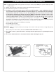
When installing the burner assembly, it is important to visually check the ODS pilot fl ame and the burner fl ames.
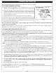
1. The ODS pilot fl ame must be present when the burner is operating. The fl ame should touch the top of the
thermocouple tip (Fig. 42-1 or Fig. 42-3).
2. If the ODS pilot fl ame does not touch the top of the thermocouple tip, then the main burner will not function
properly (see Fig. 42-2 or Fig. 42-4 for incorrect ODS pilot fl ame).
3. With the burner off and the ODS pilot fl ame off, and the assembly cool, check the burner assembly, air intake
openings on the ODS pilot, and air shutter openings on the burner for any blockages that could affect the
operation of the ODS pilot fl ame.
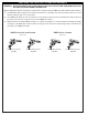
CHECKING THE ODS PILOT FLAME APPEARANCE
Incorrect ODS pilot fl ame
Fig. 42-2
Correct ODS pilot fl ame
Fig. 42-1
Incorrect ODS pilot fl ame
Fig. 42-4
Correct ODS pilot fl ame
Fig. 42-3
ODS Pilot for 01V and 15 valve
(NG shown)
ODS Pilot for 12 valve
(NG shown)