
Spec Sheet 1

41
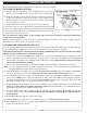
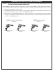
Observe the fl ames. The main burner fl ames should be blue at the base and a
combination of blue/yellow at the body and at the tips. They should be 3" to 5"
above the front logs. The ember fl ames should be 2" above the embers. The front
log should exhibit a soft glow. See Fig. 41-2.
Every Real Fyre burner system leaves the factory tested and quality checked to
ensure that it has been manufactured to the strict specifi cations to which it was
submitted and approved for certifi cation. This check includes an operational test
to ensure both satisfactory combustion and operation.
Each installation site for this appliance presents its own unique combustion environment. Specifi c factors such
as weather-tightness of the home, size of the room in which the burner system is installed, central heating,
ceiling fans, altitude, drafts, pet hair, carpet lint, dryer lint, the size of the fi replace, paint or soot inside the
fi replace, etc. all have an infl uence on the proper operation of this appliance and its ODS pilot system. A
normally operating burner system will demonstrate the following characteristics:
• A lively, realistic fl ame. The fl ame will be blue/yellow.
• Clean-burning combustion that will produce no soot or smoke after normal break-in.
• Production of no odor, other than normal odors associated with the combustion of propane or natural gas.
• Production of water vapor. Water vapor helps to increase indoor humidity, which may be benefi cial during
the dry heating season.
If you operate the burner system fueled by household propane gas, operating characteristics may vary as the
fuel in the tank approaches empty. Sooting and other increases in combustion by-products will occur. Turn off
the burner system and refi ll the propane tank.
CLEANING AND SERVICING (cont.)
Fig. 41-2
OPERATING THE BURNER SYSTEM
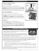
SYNCING THE REMOTE SYSTEM
12 models (if equipped)
Ensure the burner system is off and completely cool.
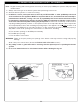
Locate the 3-position switch on the remote receiver and slide it to the
REMOTE position. Use the tip of a pen or a wire clip to push the LEARN
button and release. See Fig. 41-1. A beep will be heard. Then press
and hold the ON button on the remote transmitter; a series of beeps
should be heard. The remote system is now synced. Light burner to test.
15 models (if equipped)
Ensure the burner system is off and completely cool.
Locate the 3-position switch on the remote receiver and slide it to
the REMOTE position. Use the tip of a pen or a wire clip to push
the LEARN button and release. See Fig. 41-1. A beep will be heard.
Then press and hold the ON/HI button on the remote transmitter; a
series of beeps should be heard. The remote system is now synced.
Light burner to test.
01V models
Ensure the burner system is off and completely cool.
Locate the RESET button on the control module (attached to valve).
Press and hold the RESET button (Fig. 41-1)until you hear two acoustic
signals. After the second longer acoustic signal release RESET button.
Within the subsequent 20 seconds press the
(small fl ame) button on
the remote transmitter until you hear an additional long signal confi rming
the code is set.
LEARN
REMOTE ONOFF
Fig. 41-1 Remote receiver sync detail
12 and 15 models
01V Models