
Spec Sheet 1

35
NATURAL GAS PROPANE GAS
Outlet pressure reading:
(Flame adjustment on high)
3.5" w.c.
Outlet pressure reading:
(Flame adjustment on high)
10" w.c.
Inlet pressure reading
Max. 10.5" w.c.
Min. 5" w.c.
Inlet pressure reading
Max. 13" w.c.
Min. 11" w.c.
The burner system and its main gas valve must be disconnected
from the gas-supply piping system during any pressure testing
of that system at test pressures in excess of
1
/
2
psig (3.5 kPa).
The burner system must be isolated from the gas-supply piping
system by closing its equipment shutoff valve during any pressure
testing of the gas-supply piping system at test pressures equal
to or less than
1
/
2
psig (3.5 kPa). This is accomplished by closing
the gas-supply line valve.
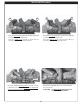
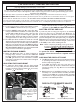
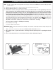
12 VALVE
Check the valve regulator pressure at the pressure inlet point
(see Fig. 35-1). Turn the inlet screw counterclockwise 2 or 3
turns and then place the tubing of the pressure gauge over the
pressure inlet point. (The test “inlet” tap is marked IN.) After
taking the pressure reading, turn the inlet screw clockwise fi rmly
to reseal. Do not over-torque. Check for gas leaks.
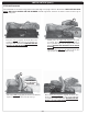
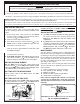
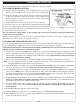
01V AND 15 VALVE
Check the valve regulator pressure at the pressure inlet point (see
Fig. 35-2). Turn the inlet screw counterclockwise 2 or 3 turns and
then place the tubing of the pressure gauge over the pressure
inlet point. (The test “inlet” tap is farthest to the gas-supply inlet.)
After taking the pressure reading, turn the inlet screw clockwise
fi rmly to reseal. Do not over-torque. Check for gas leaks.
GAS PRESSURE SPECIFICATIONS
Fig. 35-1 12 valve: check pressure
CHECK GAS PRESSURE
Outlet
Inlet
Fig. 35-2 01V & 15 valve: check pressure
Outlet
Inlet
IMPORTANT
Check the gas pressure with the
system burning and the control fully ON.