
Spec Sheet 1

19
INSTALLATION (cont.)
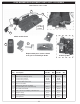
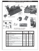
REFER TO THE PARTS LIST WHEN FOLLOWING THESE
INSTRUCTIONS.
24/30" burner model shown here.
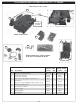
INSTALL BURNER
1. MAKE SURE THE FIREPLACE GAS SUPPLY IS TURNED
OFF.
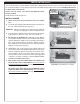
2. Locate the gas-supply stub inside the fi replace and remove
the cap, if attached (reference Fig. 19-1).
CAUTION: When removing the cap, make sure the stub does
not turn, loosening the connection inside the wall.
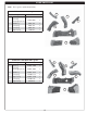
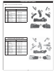
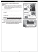
3. Place the burner system in the fi replace. Center the burner
in the fi replace. (Reference Fig. 19-2 for orientation.)
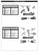
4. Be sure gas to the fi replace is off. Remove the adapter
connected to the fl ex connector (pre-installed on the burner
system). Attach the adapter to the gas-supply stub using a
pipe compound resistant to all gasses. Tighten securely.
Then attach the open end of the fl ex connector to the adapter.
Tighten securely. (See Fig. 19-1.)
5. LEAK TEST: Turn on the fi replace gas supply, and test at
all connections for leaks using the appropriate soapy water
solution. If bubbles appear, a leak is present. Turn off the
gas and tighten at all connections. Repeat until no leaks
are present. If a leak persists, turn off the gas supply and
contact the local gas company or dealer. NEVER USE A
FLAME TO CHECK FOR LEAKS.
6. 01V models only: place the battery box extension at
the front left corner of the fi replace. Place as far from
the burner system as possible. Then place the decorative
heat shield. See Fig. 19-2.
12 models only: place the wood-chip ON/OFF switch
at the front left corner of the fi replace. Place as far from
the burner system as possible. See Fig. 19-2.
Fig. 19-2 Place battery box / switch
Fig. 19-1 Connect gas supply
Flex connector
Adapter
Gas supply stub
The Real Fyre burner system must be installed by a qualifi ed professional service technician. Instructions must
be followed carefully to ensure proper performance and full benefi t from the burner system. Fireplace fl oor must
be level, clean, and smooth.
(burner)
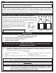
12 model shown
DO NOT
obstruct piezo
01V model only
12 model only