
Spec Sheet 1

18
WHEN USED AS A VENTED DECORATIVE APPLIANCE (PER ANSI Z21.60)
This burner system may be installed as vented decorative appliance in compliance with ANSI Z21.60 and National
Fuel Gas Code, Section 6.6. The minimum permanent free opening of the fi replace chimney or chimney damper
must be met per the Chimney Vent Opening Table on pg 3 of this manual. Chimney damper must be fi xed in a
manner to maintain permanent free opening at all times. To accomplish this, install a screw or bolt in the edge of
the damper to prevent closing, or drill holes in the damper or remove the damper.
INSTALLATION
BEFORE PROCEEDING, CAREFULLY READ ALL OF THE IMPORTANT SAFETY INFORMATION CONTAINED
IN THIS OWNER’S MANUAL, INCLUDING:
A. Pre-Installation and Fireplace Preparation Safety Guidelines
B. Ventilation and Confi ned Space Information
C. Installation Safety Guidelines
1. Adjustable open-ended wrench
2. Pliers
3. Propane gas-resistant pipe compound or Tefl on
tape
4. Soapy water solution and brush for leak detection
5. Standard screwdriver
6. Manometer (for checking gas pressure)
Tools Required:
Note: To install the unvented gas burner system, the fi replace must have a gas-supply line that has been
installed by a qualifi ed professional service technician in accordance with all local codes. Refer
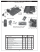
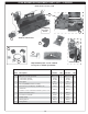
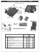
to the PARTS LIST when installing the burner system.
IMPORTANT
Be sure you have read and understand all safety precautions and warnings
contained in this manual.
WARNING: Failure to position these parts in accordance with these diagrams or failure
to use only parts specifi cally approved with this unvented burner system
may result in property damage or personal injury.
This appliance is for installation in a solid-fuel-burning fi replace (masonry fi replace or manufactured fi replace)
with a working fl ue and constructed of noncombustible material.
CHECK GAS TYPE (natural or propane). The gas supply must be the same as stated on the burner system
rating plate. If the gas supply is different, DO NOT INSTALL. Contact the dealer for immediate assistance.
WARNING
Do not connect this appliance directly to a high-pressure natural gas line or an unregulated propane tank.
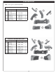
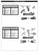
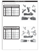
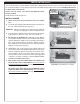
DAMPER CLAMP INSTRUCTIONS (WHEN USE AS A VENTED DECORATIVE APPLIANCE)
If the burner system is installed as a vented decorative appliance:
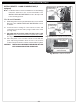
The damper clamp with hex bolt (Fig. 18-1) is provided as a means to prevent
full closure of the damper blade. The clamp is easily attached to most damper
blades with pliers or a wrench, and must be permanently installed. The clamp
is designed to prevent accidental closure of the damper when installed as
illustrated (Fig. 18-2 and Fig. 18-3). Should the
clamp not fi t, or fail to provide the permanent vent
opening specifi ed in Table 3-1, have a permanent
stop installed, remove the damper blade, or have
the damper cut to provide the minimum permanent
opening required.
Damper clamp
Fig. 18-1
Set screw
Fig. 18-2 Fig. 18-3
Open
Closed
The damper clamp is not required if the burner
system is installed as an unvented room heater.