
Installation guide

6
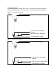
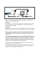
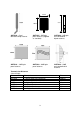
230V Mains
Power
230V Mains
Power
Camera Monitor
Transmitter Receiver
Figure 3: The most common connection diagram for setting up a simple wireless
video link using the VideoWave system.
Installation
For this section, it is assumed that the equipment has been bench tested, is working
correctly and that a site survey has been completed. If not, carry out these tests
before beginning the installation.
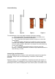
Transmitter
Start by installing the transmitter in the required location. The transmitter can either
be located inside or outside. It is housed in a weatherproof IP67 enclosure. (See page
11)
Generally, the higher the antenna can be mounted, the better the radio performance.
There are therefore two choices; mount the transmitter high with the patch antenna
connected directly to the top of the transmitter or remotely mount the antenna using a
suitable cable.
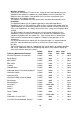
The recommended cable, LMR400, has a loss of about 0.3dB/mtr at 5.8GHz, and you
should also allow about 0.2dB for each connector. Using these figures as a guide, the
recommended maximum cable length is about 5 metres (about 2dB loss, including
connectors). Longer cables may be used, in order to clear a building or obstruction,
but in this case it may be necessary to use a higher gain antenna to compensate for
the cable loss. (see table on page 9 for antennas and cables)
Install the camera in the required position and connect to the transmitter using a 75
ohm coax cable. Connect the power to both units.
Before leaving the transmitter site, if possible, check that the unit is working correctly
using the receiver unit connected to a monitor. It may be necessary to adjust the
camera view or lens iris to obtain the clearest picture.