
Installation guide
4
Survey and Installation Guide
Before carrying out installation, it is important to bench test and familiarize yourself
with the equipment. This manual will help with antenna choice, transmission
performance, achievable distance etc.
Note: The longer the radio path the more critical details of installation become.
Bench Test
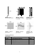
The Videowave systems is supplied as standard with an ANT5805, Patch antenna.
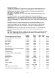
These will be sufficient for testing and for use over short to medium distances (see
table on Page 9).
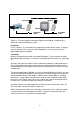
Before testing the VideoWave equipment, connect the camera to be used, directly to
the monitor with a 75 ohm cable and check for correct operation.
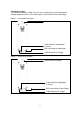
Fit the antenna to the VTX unit (transmitter) and connect the 12V dc supply (or the
mains supply in an SE version). The 7 segment LED will light indicating 'power on'
and also indicating the current selected channel. Now connect the camera to the
video input.
Note: Do not power the unit without an antenna connected. Always disconnect power
to the transmitter before connecting or removing the antenna. Failure to do so may
damage the unit.
Fit the antenna to the VRX unit (receiver) and connect the power. The 7 segment
LED will light to show 'power on' and indicate channel. Make sure the channel is the
same as the TX (if not, select the correct channel using the channel select push button
beneath the 7 segment display). The signal strength meter should also light. If the two
units are fairly close together for bench testing, all LEDs, 2 x red, 1 x orange and 3 x
green, should light. Connect the video output to the monitor. The picture should
appear on the monitor and be clear with no distortion.
System Performance
The VideoWave functions in exactly the same way as standard broadcast TV
transmissions, but on a much lower signal strength. TV aerials are normally installed
as high as possible to give the clearest signal path and achieve good reception. In
most cases if the external TV aerial is disconnected and replaced with a small indoor
aerial, the reception becomes poor. In the same way, VideoWave will always perform
best by adopting the same principle. Terrain, antenna height and signal strength will
always be the deciding factors in achieving good communications.
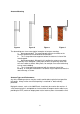
In an ideal installation 'LINE-OF-SIGHT' between the transmitter and receiver will give
optimum results (see Technical Notes). Obstacles blocking the line of sight will
reduce transmission distances and affect picture quality. The video signal may pass
through walls of brick or wood, with some degree of attenuation, but metal objects will
almost certainly block the signal; the denser the obstacles the greater their effect.
Note: Metal objects near or directly behind the antennas may also have an adverse
effect. If possible carry out a survey to establish good communications before final
installation.