
Installation guide

12
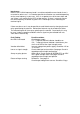
Audio and Alarms (5801 Versions)
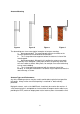
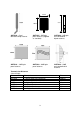
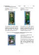
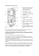
1) BNC connector on the base for
video input (transmitter) and
video output (receiver).
2) SMA antenna connector.
3) Cable gland for DC supply
4) Cable gland for audio and digital
channels.
5) DC terminal block
6) Channel number, 7 segment
display
7) Channel change push button
8) Signal strength meter (receiver
only)
9) Audio and digital terminal block
(5801 version only)
10) Link to select digital or audio for
second channel (5801 version
only)
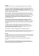
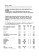
The units require a supply of 12V dc nominal (actual input range is 9 to 28V) at a
current of 75mA
for the transmitter and 215mA for the receiver.
Video input from the camera is connected to the BNC connector on the base of the
transmitter unit. Video output to the monitor, DVR etc. is from the BNC connector on
the bottom of the receiver.
There is a SMA antenna connector on the top of each unit
On the 5801 versions there is also the option of audio and digital alarm channels.
These connections should be wired through the second cable gland and connected to
the terminal block as indicated on the PCB.
The inputs for the digital alarm channels on the transmitter are volt free contacts. On
the receiver there are corresponding changeover relay outputs with contact rating 1A
@ 30V dc
The audio input on the transmitter is 1 V p-p into 100KΩ unbalanced. The receiver
output is 1 V p-p (for a 1 V p-p input) with a frequency response of 50Hz to 15KHz.
Note that the audio channel can be linked out and used as a second digital alarm
channel. This is link selectable as shown in the above diagram, position 10.