VideoWave 5.
Table of Contents System Description 3 Survey and Installation Guide 4 Antenna Mounting 8 Antenna Types 9 Transmission Distance 9 Wireless Telemetry 10 External Weatherproof Enclosures 11 Audio and Alarms 12 Technical Notes 13 Fault Finding 15 VideoWave Specifications 16 The VideoWave system is a professional quality system designed for sending composite NTSC or PAL video signals. All products comply with the R&TTE Directive 1999/5/EC.
System Description The VideoWave Wireless Video Transmission is a professional system designed for sending composite NTSC or PAL video signals using 5.8 GHz wireless technology.
Survey and Installation Guide Before carrying out installation, it is important to bench test and familiarize yourself with the equipment. This manual will help with antenna choice, transmission performance, achievable distance etc. Note: The longer the radio path the more critical details of installation become. Bench Test The Videowave systems is supplied as standard with an ANT5805, Patch antenna. These will be sufficient for testing and for use over short to medium distances (see table on Page 9).
Site Survey It is advisable to carry out a survey to establish a good radio path prior to installation. This will help with the positioning of the equipment and choice of antenna. Your distributor should be able to assist with information and may be able to provide a Survey Kit and antennas for this purpose. Before commencing a survey, measure or estimate from a map, the straight-line distance between the two sites.
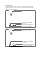
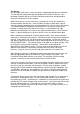
Transmitter Camera Receiver Monitor 230V Mains Power 230V Mains Power Figure 3: The most common connection diagram for setting up a simple wireless video link using the VideoWave system. Installation For this section, it is assumed that the equipment has been bench tested, is working correctly and that a site survey has been completed. If not, carry out these tests before beginning the installation. Transmitter Start by installing the transmitter in the required location.
Receiver Installation of the receiver unit is basically a repeat of the transmitter installation. The antenna selection will depend on the distance from the transmitter site and the results of the site survey. The standard patch supplied is suitable for distances of up to about 1Km maximum (depending on local conditions). Other antennas are available for distances up to about 3Km. (see table on page 9). Note: The higher gain antenna should be fitted to the receiver.
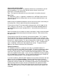
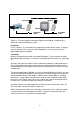
Antenna Mounting Figure a Figure b Figure c Figure d The above diagrams show some typical examples of antenna mounting. a. Not recommended. The mounting pole will have an effect on the antennas performance and could cause reflections. b. This is the preferred arrangement where the antenna is clear of the mounting pole. c. Not recommended. Although in this position the antenna may work, especially if the radio path is away from the wall, the proximity of the wall can cause adverse effects.
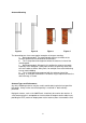
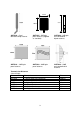
7.5cm 50cm 10cm ANT5803 – Omnidirectional whip antenna. ANT5805 – 5dB gain patch antenna (supplied as standard). ANT5808 – 8dB gain omni-directional dipole antenna, ANT5810 – 10dB gain panel antenna ANT5820 – 20dB gain panel antenna ANT5828 – 28dB gain parabolic dish antenna Transmission Distances (Line-of-Sight) Antenna Description Distance ANT5803 ANT5805 ANT5808 ANT5810 ANT5820 ANT5828 500mtrs 1Km 1Km 1.
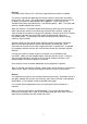
Wireless Telemetry Telemetry for controlling PTZ cameras etc. cannot be transmitted directly over the VideoWave but requires the addition of a Radio Modem to transmit the data. The RM96XX series of modems is designed for use in the license free bands and is approved for all European countries. The modem is compatible with most commercially available video telemetry units. Installation The RM96XX modem can be supplied separately or mounted alongside the VideoWave unit in an IP67 enclosure.
Vista Powerdome IP67 Weatherproof Enclosures RS485 9600 8 1 None Enclosure for VideoWave Transmitter or Receiver Model VTX/VRX5800S Enclosure for VideoWave Transmitter or Receiver Model VTX/VRX5800SE The enclosure has a SMA antenna connector on the top and a BNC for video on the bottom. Cable glands are provided on the bottom for 12Vdc and alarm /audio cables. (These options are available on the 5801 versions) The enclosure has a SMA antenna connector on the top and a BNC for video on the bottom.
Audio and Alarms (5801 Versions) 1) BNC connector on the base for video input (transmitter) and video output (receiver). 2) SMA antenna connector. 3) Cable gland for DC supply 4) Cable gland for audio and digital channels.
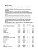
Technical Notes Propagation/Distance For any radio link, the distance that can be achieved between sites depends on a number of factors, the main ones being; the output power, the antenna height (above ground), the type of terrain and ‘line-of-sight’. Line-of-sight means how clear the path is between the two antennas, whether there are any obstructions and how dense these obstructions are. The major effect on distance however, is the height of the antennas above ground.
Reflections The best possible performance and therefore distance, will be achieved if there is perfect unobstructed line-of-sight between the two sites ‘A’ and ‘B’. Even in this situation however there is almost certain to be some degree of reflections from the ground or nearby structures. These reflections will have an effect on the signal strength and the final picture quality obtained. It is useful therefore to understand the basic principals of a radio link and the effect of reflections.
Interference Because the 5.8 GHz frequency band is an unlicensed public access bands, there is no control on other users. It is therefore possible that another user could be operating on the same frequency in your area. If this is suspected, turn off the transmitter and see if there is any activity on the LED’s of the receiver. If there is a transmission on the same frequency the amber or green LED’s should light or flash indicating the received signal.
Specification General Video Input 1V p-p into 750ohm BNC Video Output 1V p-p into 750ohm BNC Operating Voltage 240V AC Protection Reverse Polarity Power Consumption @ 240V AC Transmitter 1W Receiver 2.6W Antenna Connector 50ohm SMA (Female) Power Connector Screw terminal Indicators Channel / ON 7 segment display Signal Strength (RX) LED bar graph Radio Modem Frequency Range Channel Spacing No. of Channels Transmitter RF Power Output Adj. Channel Power Freq.