
User manual


3
Additional Information
Power Supply
The RM96xx board requires a 12V d.c. power supply
which should be well filtered and regulated. On-
board voltage regulator circuits will maintain a
constant supply of voltage to the radio and logic
circuits, however, excessive noise, fluctuations and
interference on the d.c. supply may cause loss of
data.
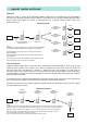
Antenna Selection
The antenna should be designed for use at the
operating frequency in the 406-470MHz UHF
frequency band. The radio range achieved will be
dictated by the land topography between the nodes.
Ranges quoted below are for guidance only,
distances vary according to terrain and obstructions.
In many situations increasing atenna height can
greatly improve signal strength, and the RSSI test
mode can be used for signal strength indicated.
Yellow LEDs indicate minimum acceptable signal,
green LEDs indicate excellent signal strengh.
Coaxial feeder cable is available in many forms, 50
ohm impedance cable with low loss should always
be used, note that 3dB of feeder loss will reduce
radiated power by half. In some applications where
maximum range is required, directional antennae
with gain can compensate for feeder loss provided
that the maximum radiated power limit is not
exceeded.
When low loss RG213/U or UR67 coaxial cables are
employed N-type RF connectors should be fitted in
conjunction with one of the Antenna Bulkhead Cable
Kits to convert from the SMA of BNC socket on the
radio module to N-type RF connectors on the
coaxial cable.
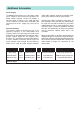
Antenna Type Range Coverage Gain Mounting Applications
1
/
2
-Wave Whip 1 km Omnidirectional -3dB Enclosure Mounted Short range general use
End-fed Dipole 10 km Omnidirectional 0dB Pole Mounted Medium range general use
8 Element Yagi 20 km Directional (40°) 10dB Pole Mounted Long range, directional
Antenna Types