
User manual


17
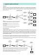
.... timing diagrams continued
TXD
Data
TX
RX
Radio
RTS
CTS
RXD
TX
RX
Radio
Data
Header
Block
Data 3
1 = Transceiver lock time &
Transmitter power up
= 10 mS max.
2 = Time varies with quantity of
data still to Transmit.
3 = Transceiver lock time TX to RX
= 10 mS max.
1
CTS
RTS
2
Transmitter
Receiver
Fig. 7 Modem Mode Transmit/Receive Timing Diagram
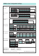
RM9600
General
Frequency Range
10MHz band in the range
406 - 470 MHz
Channel Spacing 10, 12.5, 20 or 25kHz
Transmitter
RF Power Output 50 - 500mW (in 4 steps)
Adj. Channel Power -37dBm
Freq. Tolerance ± 3ppm
FM Deviation ± 3.5kHz
Receiver
RF Sensitivity - 110dBm for 10
-4
BER
Intermodulation -70dB
Adj. Channel Rejection -70dB
RM9634
General
Frequency Range 10MHz band in the range
406 - 470 MHz
Channel Spacing 12.5, 20 or 25kHz
Transmitter
RF Power Output 50 - 500mW (in 4 steps)
Adj. Channel Power -37dBm
Freq. Tolerance ± 1kHz
FM Deviation ± 2kHz
Intermod Attenuation >40dB
Spurious Emissions <-36dBm 0-1 GHz
<-30dBm 1-4 GHz
Receiver
RF Sensitivity - 110dBm for 10
-4
BER
Co-channel Rejection >-12dB
Adj. Channel Selectivity >60dB
Spurious Response Rejection >70dB
Intermod Response Rejection >70dB
Blocking >84dB for any signal >50kHz from
the tune frequency
Spurious Emissions <-57 dBm 0-1 GHz
<-47dBm 1-4 GHz
Specifications – Specific Models
Specifications – All Models
RSSI Threshold Level -105dBm at 16K
-110dBm at 8K/4K
Max. Bit Rate 16kbps (25KHz)
8kbps (10/12.5/20KHz)
Modulation GMSK
Interface Baud Rate 150-19.2 Kbaud, adjustable
Parity Odd, Even or None
Data Buffer 4 Kbytes Tx, 2 Kbytes Rx
Stop Bits 1 or 2
Data Bits 7, 8 or 9