
User manual


13
User Controls
Factory Settings
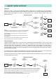
The RM96xx is shipped from the factory pre-pro-
grammed to operate with the following settings:-
Serial Port
Mode Async, FEC On
Listen Before Tx ON
Serial Port RS232
Baud Rate 9600
Parity None
Data Bits 8
Stop Bits 1
RF Parameters
RF Channel 1
Power Level 500mW
Address 0
RF Data Rate 16K
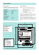
User Configuration
Settings are altered by following 3 simple steps:-
1. Adjust Rotary switch (SW2) for desired
function (see table 1)
2. Select required parameters using DIL
switch (SW1)
3. Press 'STORE' button (SW3)
The above steps may be repeated for each Rotary
Switch function indicated in the table on page 14.
(refer to notes for exceptions to this rule)
To ease configuration, LED indicators D10-D17
display the current stored DIL switch settings for
each rotary switch function, excluding functions '0'
and '1'.
FIG. 2 RM96xx Radio Modem Board Layout
C
1 2 3 4 5 6 7 8
ON
UHF Synthesised
FM Transceiver
Type IRDN031/0
Frequency Range
ERP
406 to 470 MHz
500 mW max.
Made in England
Radio Data Technology Ltd
Radi o Data Techn ology LTD 1996 RM9600/1
109 mm
99 mm
120mm
130mm
4 x Mounting holes are M3 (3mm)
SW1
SW2
SW3
D17
RS232
RS485 Supply
D10
D1 D8
1
2
3
+12V
GND
DC
LED FUNCTIONS (Run Mode)
D10 Carrier Detect
D11 Buffer Full
D12 Receive Serial Data
D13 Transmit Serial Data
D14 RF Receive
D15 RF Transmit
D16 Supply Voltage
D17 Supply Voltage
LED FUNCTIONS (All Modes)
Red=LOW (< -5v)
Green=HIGH (> +5v)
D1 CTS (input to RM9600)
D2 DSR (input to RM9600)
D3 DCD (output from RM9600)
D4 RxD (input to RM9600)
D5 TxD (output from RM9600)
D6 DTR (output from RM9600)
D7 Spare (reserved)
D8 RTS (output from RM9600)