RDT RM96xx Radio Modem Series User Manual
Table of Contents Main features and brief description . . . . . . . . . . . . . . . . . . . . . . . . . . . . . . . . . . . . . . . . . . . . . . . . . . . . . 2 Additional Information on Power Supplies/Antennas . . . . . . . . . . . . . . . . . . . . . . . . . . . . . . . . . . . . . . . . 3 Modes of Operation Primary Modes . . . . . . . . . . . . . . . . . . . . . . . . . . . . . . . . . . . . . . . . . . . . . . . . . . . . . . . . . . . . . . . 4 Repeater Modes . . . . . . . . . . . . . . . . . . . . .
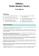
RM96xx Radio Modem Series User Manual Features ● UHF FM Synthesised Radio Transceiver ● Transparent serial data transmission ● ● ● User selectable RF channel, Address and Tx power level RS-232 & RS-485 Serial Data Interfaces ● LED indicators for radio functions, signal strength and serial line status 6 modes of operation including Asynchronous, Modem and Repeater ● Forward Error Correction (FEC) ● Automatic Repeat Request (ARQ) Brief Description The RM96xx Series of Radio Modems are a range
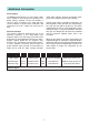
Additional Information Power Supply The RM96xx board requires a 12V d.c. power supply which should be well filtered and regulated. Onboard voltage regulator circuits will maintain a constant supply of voltage to the radio and logic circuits, however, excessive noise, fluctuations and interference on the d.c. supply may cause loss of data. Yellow LEDs indicate minimum acceptable signal, green LEDs indicate excellent signal strengh.
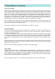
Primary Modes of Operation Asynchronous Mode In Asynchronous Mode data arrives through either the RS-232 or RS-485 serial port and is placed in the data buffer. As soon as data is detected in the buffer, the transceiver is switched to transmit mode. Once switched to transmit there will be a short delay (10mS), while the synthesiser locks and the transmitter reaches operating power. The data buffer is then inspected to determine the number of bytes available for transmission in this data packet.
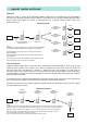
Repeater Modes From time to time it is necessary to include a repeater in a system for the following reasons:• To extend range • To circumvent obstacles • Achieving a radio link where circumstances dicate the use of less efficient antennas A system using a repeater is inherently more complex than one without and it is recommended that first time users may wish to discuss the details of system operation with their modem supplier.
... repeater modes continued Repeat All Repeat All mode is similar to the Standard Repeater mode with the exception that all valid RM96xx messages are repeated regardless of their address. This permits the use of a base station operating under Serial Control and enables the master to communicate with a specific remote modem rather than broadcasting to all.
Serial Control Mode Introduction Selecting Serial Control mode permits various Radio Modem parameters to be interrogated and modified via the serial port instead of using the on-board DIL switches. In some applications the user equipment takes care of addressing in which case an RM96xx operating in one of the standard modes can be utilised to provide a straight forward transparent serial data link.
... serial control mode continued Configuring the RM96xx Setting Serial Control Mode Select Serial Control mode by turning the rotary switch (SW2) to position 3 and switching DIL switch SW1 position '3' to the 'ON' position. Ensure that all the remaining DIL switches are set to the required positions before pressing the STORE button (SW3) to activate the settings. Return the rotary switch to the '0' position when all options are configured.
... serial control mode continued Command Format Serial Control mode allows the user to set or enquire about the value of an Address or RF Channel number.
User Controls Factory Settings User Configuration The RM96xx is shipped from the factory pre-programmed to operate with the following settings:- Settings are altered by following 3 simple steps:- Serial Port Mode Listen Before Tx Serial Port Baud Rate Parity Data Bits Stop Bits Async, FEC On ON RS232 9600 None 8 1 RF Parameters RF Channel Power Level Address RF Data Rate 1 500mW 0 16K 1. Adjust Rotary switch (SW2) for desired function (see table 1) 2.
RM96xx User Configurable Settings ROTARY SWITCH = 0 1 2 RF POWER OFF OFF OFF ON ON OFF ON ON RUN MODE SWITCH SW1 3 4 50mW 100mW 250mW 500mW OFF OFF etc. ON 5 6 RF CHANNEL OFF OFF OFF OFF etc. etc. ON ON SWITCH SW1 3 4 5 Receive Transmit OFF OFF etc. ON OFF OFF etc. ON OFF OFF etc. ON 7 8 OFF OFF etc. ON OFF ON etc. ON LOWEST FREQ HIGHEST FREQ ROTARY SWITCH = 1 1 2 TEST MODE OFF ON - TEST ROTARY SWITCH = 2 ADDRESS OFF OFF etc. ON 1 2 3 OFF OFF etc. ON OFF OFF etc. ON OFF OFF etc.
Timing Diagrams Transmitter Receiver Fig. 3 Asynchronous Mode Transmit/Receive Timing Diagram Transmitter Receiver Fig. 4 Asynchronous ARQ Mode Transmit/Receive Timing Diagram Transmitter Receiver Fig. 5 Synchronous Mode Transmit/Receive Timing Diagram Transmitter Receiver Fig.
.... timing diagrams continued Transmitter Data RXD CTS RTS TX Radio RX 1 Receiver Header Block Data 3 2 1 = Transceiver lock time & Trans mitter pow er up = 10 mS max . 2 = Time var ies with quantity of data still to Tr ansmit. 3 = Transceiv er lock time TX to RX = 10 mS max . R TS C TS TX Radio RX TXD Data Fig.
.... specifications continued Mechanical & Environmental Power Supply Size RM96xx RM96xxB RM96xxE/EX Weight RM96xx RM96xxB RM96xxE/EX Operating temperature Operating humidity RM96xx/B Power Supply Supply Current 130 x 109 x 32mm 142 x 150 x 47mm 280 x 190 x 130mm RM96xxE/EX Power Supply Supply Current 400 g 900 g 3.6 kg -25 to +60°C 20% to 75% RH 10.5 - 15.5V d.c. Tx 550mA (500mW) Rx 260mA 220-260V a.c. 50Hz 250mA max a.c.