
User Manual
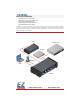

POWER CONNECTION
FIXED MOUNTING RUBBER FEET ATTACHMENT
Insert Power Plug
Bottom View
of chassis
Recess
Screw
directly to flat
surface without
installing rubber feet.
Rotate 1/4-turn
clockwise to lock
Rotate 1/4-turn
counter-clockwise
to unlock
Peel backing and stick the 4 rubber
feet to chassis in recesses provided.
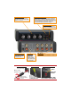
24 V POWER INPUT
Insert plug from power
supply. Rotate 1/4 turn
clockwise to lock.
LINE INPUTS
Connect a line-level source to LINE INPUT 1, 2, 3 and/or 4.
POWER INDICATOR
Glows blue when the product is
connected to a valid power source.
LINE INPUT LEVELS
Adjust for the desired sound level
from the sources connected to LINE
INPUTs 1, 2, 3 and 4.
STEREO OUTPUT VU METERS
LEFT and RIGHT LED VU meters monitor the unbalanced
outputs for proper -10 dBV level. With audio present, the
variable intensity green LED should be as bright as possible
with the red LED flashing occasionally. (The red LED
flashes when the output level exceeds -10 dBV.)
LINE OUTPUT
Connect to the
line input of an
amplifier, mixer,
recorder, computer
or other product with
a line-level input.
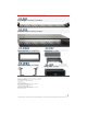
POWER CONNECTION
FIXED MOUNTING RUBBER FEET ATTACHMENT
Insert Power Plug
Bottom View
of chassis
Recess
Screw
directly to flat
surface without
installing rubber feet.
Rotate 1/4-turn
clockwise to lock.
Rotate 1/4-turn
counter-clockwise
to unlock.
Peel backing and stick the 4 rubber
feet to chassis in recesses provided.