
Installation Guide

5
(Fig. 12)
(Fig. 13)
(Fig. 14)
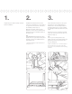
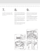
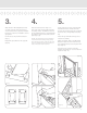
7.
If you did not cut the top rail in steps 3
and 4, do so now following the same
procedure you used in steps 3 and 4 for
the bottom rail.
8.
Place a T-shaped mounting bracket on
each end of the top rail, with the at side
facing the mounting surface. Slide the
bracket back past the rst baluster hole
(Fig. 12).
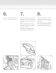
Make sure that the aluminum T-channel
is ush with the end of the vinyl top rail.
Use a 7/32" drill bit to drill through both
ends of the top rail and aluminum T-
channel. The hole should be 5/16" from
the end and 7/16" from the bottom of
the rail.
Place an aluminum retaining pin through
the hole. Slide the bracket over the pin
to the end of the rail (Fig. 13).
9.
Beginning at one end of the rail section,
(Fig. 14) insert each baluster installed in
Step 6 into the corresponding baluster
hole in the top rail.
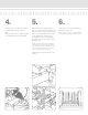
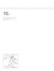
To allow for baluster expansion, raise the
top rail approximately 1/8". Pre-drill the
holes (Fig. 15) for the mounting brack-
ets to avoid stripping the stainless steel
screws and secure in place (Fig. 16).
Repeat Steps 6 through 9 for each rail
section.
(Fig. 15) (Fig. 16)