
Installation Guide

4
(Fig. 11)
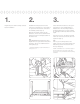
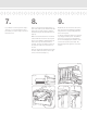
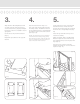
4.
Cut each end of the rail at the measure-
ment determined in Step 3 (Fig. 7).
Tip:
If using a power saw, a carbide tip blade
of at least 60 teeth is recommended.
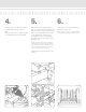
5.
Place a Bottom Mounting Bracket on
each end of the Bottom Rail with the at
side facing the mounting surface (Fig. 8).
Place on the marks determined in Step
2. Pre-drill the holes (Fig. 9) for the
mounting brackets to avoid stripping
the stainless steel screws and secure in
place (Fig. 10).
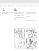
NOTE: The looped part of the aluminum
P-channel must be facing away (down)
from the baluster holes while the at side
of the P-channel must be facing the out-
side of the deck when mounted.
Repeat Steps 3 through 5 for each rail
section.
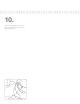
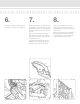
6.
Insert a baluster in each routed hole of
the bottom rail (Fig. 11).
NOTE: Each kit contains 2 crimped balus-
ters, space them evenly in each section.
(Fig. 7)
(Fig. 8)
(Fig. 9) (Fig. 10)