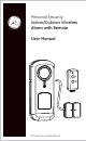
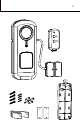
Personal Security Indoor/Outdoor Wireless Alarm with Remote User Manual A rm Disarm Do not use in wet locations
Table of Contents Introduction 3 Installing Batteries 6 Low Battery Indicator Light 7 Linking the Alarm 8 Installation 11 Arming the Alarm 14 Disarming the Alarm 15 Care and Maintenance 16 Battery warnings 17 FCC Warning 17
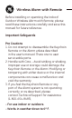
Wireless Alarm with Remote Before installing or operating the Indoor/ Outdoor Wireless Alarm with Remote, please read these instructions carefully and save this manual for future reference. Important Safeguards Pre Cautions 1. Do not attempt to disassemble the Keychain Remote or the Alarm unless described in the user’s manual. There are no user serviceable parts. 2. Handle with Care – Avoid striking or shaking. Improper use or storage could damage the Keychain Remote or the Alarm.
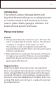
Introduction The Indoor/Outdoor Wireless Alarm with Keychain Remote allows you to add protection or monitor areas in and around your home. Use on gates, sheds, garages, cabinets, tool boxes and personal truck boxes. Please note below: Remote: 1. The Keychain Remote will transmit up to 30ft from the Alarm.
A rm Disarm
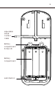
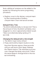
Adjustable Wired Contact Cable Battery Compartment Screws (2) Battery Compartment Learn Button
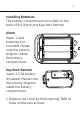
Installing Batteries The battery compartment is located on the back of the Alarm and Keychain Remote Alarm Insert 3-AAA batteries (not included). Please note the polarity diagram inside the battery compartment. Keychain Remote Insert 1-2 3A battery (included). Please note the polarity diagram inside the battery compartment. 1. Replace the cover by first inserting TABS at base and secure screws.
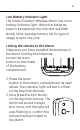
Low Battery Indicator Light The Indoor/Outdoor Wireless Alarm has a low battery indicator light. When the batteries need to be replaced, the indicator will flash slowly. Note: Average battery life for typical usage is up to one year. Linking the remote to the Alarm Make sure you have installed the batteries in the Alarm and Keychain Remote. Locate the learn button on the inside of the battery compartment . 2. Press the learn button in the battery compartment as seen above.
Note: additional remotes can be added to the system by following the same programing procedure. 4. Replace cover to the battery compartment by first inserting tabs of battery compartment cover and secure screws. Delayed Entry Time The Alarm defaults delay is one second. This is the amount of time the Alarm will delay once triggered. (i.e. door opened when Alarm is set). There is an alternate delay setting of 5 seconds. Changing the delayed entry time length 1. The Alarm must not be armed. 2.
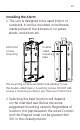
Installing the Alarm 1. The unit is designed to be used indoor or outdoors. It can be mounted in toolboxes, inside personal truck boxes or on gates, sheds, and doors etc. Anchored screws mounting Double sided mounting tape The mounting surface will determine whether to use the double-sided tape or mounting screws. DO NOT USE screws if mounting surface is less than two inches thick. 2. Selecting the best location will depend on the intended use. Below are some suggested mounting options.
Tool boxes or Personal truck boxes Inside of truck boxes or toolboxes - use the two sided installation tape included
Cabinets, Slidiing Doors and Doors Inside of doors - use the two sided installation tape included or if the mounting surface is over two inches thick Use the anchors and screws provided.
Gates Inside of gates - use the two sided installation tape included or if wood is over two inches thick use screws included. The Alarm is weather resistant so it can be mounted outside. The preferred location is to mount the Alarm and wired Contact on the gate and the Magnet to the fixed post or wall. When mounting to a wood or porous surface, you can use the extra mounting plates.
Remove Mounting plate will snap to lock in place. Note: To remove the Alarm, push locking TAB, lide the Alarm upwards off the mounting plate. Attach up to 3/4" space between magents Use the provided doublesided stick tape, to mount to most surfaces. For porous Line up surfaces use optional arrows mounting plates. Aligning the Wired Contact & Magnetic Contact After the Alarm is mounted on mounting bracket the Magnetic Contacts need to be aligned. See above.
Arming the Alarm After either Arm or Disarm button is pressed, the Keychain Remote will transmit for approx two seconds. There is a two second delay before the remote can transmit a new command (pressing another button). 1. Locate arm/disarm button on the front of the remote. 2. The wireless remote will operate the Alarm up to 30 ft. The wireless range will vary depending on the number of walls, appliances or obstructions between the Alarm and remote.
4. When the magnet and wired contact are separated (door or lid opened), the red indicator on the front of the Alarm will begin flashing indicating the Alarm has been activated. The Alarm’s siren will begin sounding within 1 second or 5 seconds (depending on the delay entry time setting). The Alarm will continue to sound until disarmed by a linked remote. Disarming the Alarm: 1. If the Alarm has been activated, press the disarm button to disarm the Alarm. 2.
Note: to test, a cloth can be used to cover the Alarm to reduce risk of hearing damage. Care and Maintenance To clean the unit housing, use a soft cloth slightly dampened with water and wipe dry. Do not use chemical agents as this may damage and discolor the unit.
WARNING Limitations of Alarm Products This product should be tested periodically to make sure it is working properly. The product, if used properly, may reduce the risk of burglary, robbery, or other adverse events. However, JASCO is not an insurer, this product is neither insurance nor a guarantee that such an event will be prevented, and users should protect themselves with proper insurance.
FCC Warning Functional range may be adversely affected by one or more of the following factors: weather, radio frequency interference, low transmitter battery and obstructions between the transmitter and receiver. This device complies with part 15 of the FCC rules. Operation is subject to the following two conditions: (1) this device may not cause harmful interference, and (2) this device must accept any interference received, including interference that may cause undesired operation.