
Specifications

ALIGNMENT PROCEDURE (Continued) 721TS
ORDER
OF ALIGNMENT—When
a
complete receiver
alignment
is necessary, it
can be most conveniently periormed in
the
following order:
Sound discriminator
Sound i-f transformers
Picture i-f traps
Picture i-f coils
R-F and converter lines
R-F
oscillator
line
Retouch picture i-f transformers
Sensitivity check
SOUND DISCRIMINATOR
ALIGNMENT—
Set
the signal generator
for
approximately .1 volt
output at
21.25 mc. and connect it to the second sound i-f grid.
Detune
T108
secondary (bottom).
Set the "VoltOhmyst"
on
the
10 volt scale.
r
Connect the
meter
in series with
a one
megohm resistor
to the
junction
of diode resistors R181 and R182.
Adjust the primary of
T108
(top) for maximum output
on the
meter.
Connect the "VoltOhmyst" to pin 1 of V118 and
set on the
3
volt scale.
Adjust T108 secondary (bottom). It will be found that it is pos-
sible
to
produce
a
positive or negative voltage on the meter
de-
pendent upon this adjustment. Obviously to pass from
a
posi-
tive to
a
negative voltage, the voltage must go through zero.
T108 (bottom) should be adjusted so that the meter
indicates
zero
output as the voltage
swings from positive
to
negative.
This point will
be
called discriminator zero output.
Connect the sweep oscillator to the grid of the second sound
i-f amplifier.
Adjust the sweep
band
width
to
approximately
1 mc. with
the center frequency at approximately 21.25
and with
an
output of
approximately .1 volt.
Connect
the
oscilloscope
to pin 1 of V116.
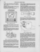
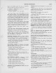
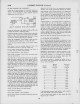
The pattern
obtained should be similar to that shown in
Figvure 13A. If
it U not, adjust T108 (top) until the wave iorm
is
symmetricaL
The peak to
peak bandwidth
of
the discriminator should be
opproximotely
350 ke. and should be linear from 21.175
mc.
to
21.325
mc.
SOUND
IF ALIGNMENT—
Connect
the sweep and signal
generator to the
top end
of
the
trap winding of T3 (on top of the chassis).
Connect the oscilloscope
to the second sound
if grid
return
(terminal A T107) in series with
a
33,000 ohm isolating resistor.
Connect
a
5600
ohm
resistor from terminal A,
T107 to
ground.
Insert
a
21.25
mc.
marker signal from the signal generator
into the first sound if grid.
Adjust T107 (top and bottom)
for maximum gain and sym-
metry about
the
21.25
mc.
marker. The pattern obtained should
be
similar
to
that
shown
in Figure 13B. The band width at
80% response from the first sound i-i
grid to
the
second i-f grid
should
be approximately 250 kc.
The output level from the sweep should be set to
produce
approximately .3 volt peak-to-peak
at
the
second sound i-f grid
return when
the
final touches on the above
adjustment are
made.
It is necessary that the sweep
output voltage should
not exceed
the
specified values
otherwise the
response
curve
will be
broadened,
permitting
slight
misadjustment
to pass
unnoticed and
possibly
causing
distortion on
weak
signals.
PICTURE
IF
TRAP ADJUSTMENT—
Connect the
"VoltOhmyst" to the
junction
of R106 and
R107
and adjust the
picture
control
for
-3
volts on the
meter.
Set the
channel switch to
channel
13.
Connect the
"VoltOhmyst" across the
picture
second detector
load
resistor
RI18 and set it on the
3 volt scale.
Connect
the
output of the
signal generator to the
junction of
C14 and
R8.
This
connection is
available on
a
terminal
lug
through a hole in the side
apron of the chassis,
beside the r-f
unit.
Set the generator to 21.25 mc.
and check it against a
crystal
calibrator
to
insure that the generator is
exactly on frequency.
Adjust T3 (top) and TlOl for minimum
indication on the
"Volt-
Ohmyst."
Set
the
generator
to
27.25
mc and adjust T104 secondary (bot-
tom)
for
minimum indication on the "VoltOhmyst" {this adjust-
ment is omitted on some chassis).
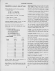
PICTURE I-F COIL ADJUSTMENTS—
Set the
signal generator to each
of the
following frequencies
and
peak the specified
adjustment for
maximum
indication
on
the
"VoltOhmyst."
22.8
mc—T3 (bottom)
23.9 mc.—
LlOl (top of chassis)
26.0 mc.
—
^T104 primary (top
of chassis)
24.5 mc.—L103 (top
of
chassis)
Picture I-F
Oscillation
—
If
the
receiver is badly misaligned
and
two or
more of the i-f coils are tuned to the
same frequency,
the
receiver may fall into i-f
oscillation. I-F oscnllation
shows
up
as a
voltage in excess of 3
volts at the picture
detector
load resistor.
This voltage is unaffected by
r-f signal
input
and sometimes is independent
of picture control
setting.
If such a condition is
encountered, it is
sometimes
possible
to
stop oscillation by
adjusting the coils
approximately to
fre-
quency by
setting
the
adjustment stud
extensions of T3.
LlOl, T104 and LI03 to be
approximately
equal to those
of
another
receiver known to be in
proper
-
alignment.
If this
does not have the desired
effect, it may now be
possible
to stop oscillation by
increasing the grid bias.
If so, it should
then be possible to
align the coils by the
usual method.
Once
aligned in this manner, the
i-f should be
stable with
reduced bias.
If the os<dllation cannot be
stopped in the above
matmer,
shunt the
grids
of the first two i-f
amplifiers
to
ground with
1000
mmf.
capacitors.
Connect the signal generator to the third
i-f grid and adjust
L103 to frequency.
Remove
the
shunting capacitor from the second i-f grid,
connect
the signal generator to this grid
and align T104.
Remove the shunting capacitor from the
first i-f
grid,
connect
the signal generator
and
align
LlOl.
Coimect the signal generator to the junction of C14 and R6
(in
the r-i tuning luit) and align T3 to
frequency.
B this does not stop the osdllation, the difficulty is not due
to i-f misaligiunent
as the
i-f
section is
very stable when prop-
erly aligned. Check all
i-f
by-pass
condensers, coil
loading
resistors,
tubes, socket voltages, ete.