
Specifications
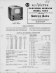

721TS
ALIGNMENT
PROCEDURE
TEST
EQUIPMENT
—To service this
receiver properly,
it is
recommended
that
the following test
equipment
be
available:
R-F Sweep Generator
meeting
the following
requirements:
(a)
Frequency
ranges:
18 to 30 mc,
1 mc sweep width
40
to 90 mc, 10 mc sweep width
170 to 225
mc, 10 mc sweep width
(b) Output
adjustable with
at least .1 volt maximum.
(c) Output constant on all
ranges.
(d) "Flat" output
in all attenuator positions.
Cathode-ray Oscilloscope,
preferably
one with
a
wide
band
vertical deflection
and an input calibrating
source.
Signal
Generator to provide
the following frequencies:
(Output on these ranges should
be adjustable
and at least
.1
volt maximum.)
(a)
Intennediate
frequencies:
21.25 mc
sound M
and sound
traps
22.8
mc converter
transformer
23.9 mc first
picture i-f
coil
24.5
mc third picture
i-f coil
26.0
mc second
picture i-f
primary
27.25
mc second
picture i-f
secondary
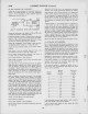
(b)
Radio
frequencies:
Picture
Sound
Channel
Carrier
Carrier
Number
Freq. Mc Freq.
Mc
1 45.25
49.75
2
55.25 59.75
3
61.25
65.75
4 67.25
71.75
5 77.25
81.75
6
83.25 87.75
7
175.25
179.75
8 181.25
185.75
9 187.25
191.75
10
,
193.25
197.75
11 199.25
203.75
12
205.25
209.75
13
211.25
215.75
Heterodyne Frequency
Meter with crystal calibrator
if the
signal generator is not crystal controlled.
Electronic
Voltmeter of
"Junior VoltOhmyst
type" and a high
voltage probe for
use with this meter to permit measurements
up to 10 kr.
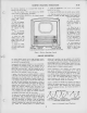
SERVICE
PRECAUTIONS—
Cutouts in
the
bottom of
the cabinet
make
it
possible to
do some
of the
servicing
of the
receiver
without
removing
the
chassis.
If the receiver
is serviced
in
the
cabinet,
a soft pad
should
be placed
under
the
cabinet
when it
is inverted,
in
order to
avoid scratching
the surface.
In manufacture,
the
cabinet
receives
a
Class
1 rub
finish
and
every effort
should
be made
to preserve
that
finish.
If
necessary to
remove
the chassis
from
cabinet,
the kinescope
must first
be removed.
See Figures
3, 4
and
6. If possible,
the chassis
should
then
be serviced
without
the
kinescope.
However, if
it is necessary
to
view
the raster
during
servicing,
the
kinescope
should
be inserted
only
after the
chassis
is
turned
on end. The
kinescope
should
never
be allowed
to
support
its weight
by resting in
the deflecting
yoke.
A
bracket
should
be used to
support
the tube
at its viewing
screen.
By
turning
the
chassis
on end with
the power
transformer
"up," all
adjustments
will be
made conveniently
available.
Since
this
is the only
safe position
in which
the
chassis will
rest
and
still
leave
adjustments
accessible,
the trimmer
location
drawings
are oriented
similarly
for ease
of use.
CAUTION:
Do not permit
the kinescope
second-anode
lead
to become
"shorted" to the
chassis. To
do so will
cause
a
considerable overload
on the high-
voltage filter
resistor
HI 87.
ADJUSTMENTS REQUIRED
Normally,
only the
r-f oscillator
line
will require the
attention of
the service technician.
All
other circuits
are either broad
or very stable
and hence
will
seldom require
readjustment.
Due to the high frequencies
at which
the receiver
operates,
the r-f oscillator-line
adjustment is critical
and may be
affected
by a
tube
change. The line can be adjusted
to the proper
fre-
quency on channel
13
with
practically any
6J6
tube in the
socket. However, it
may
not then
be possible
to adjust the
line to frequency on all of channels
7, 8, 9, 10,
11, and 12.
For an
oscillator
tube to be satisfactory, it should
be possible
to adjust the line to proper frequency
with the fine-tuning
control in the middle of its range. It
may
therefore
be neces-
sary to select
a
tube for the oscillator socket.
In replacing, if
the old tube can be matched for frequency
by trying several
new ones,
this practice
is recommended. At best,
however,
it
will probably
be
necessary
to realign the oscillator line
completely after changing the tube.
Tubes which cannot be used
as
an oscillator may work satis-
factorily as an r-f amplifier or
a
converter.
The detailed alignment procedure which follows is intended
primarily as
a
discussion of the method used, precautions
to
be taken, and the reasons
for
these precautions. Then, for
more
convenient reference during alignment,
a
tabulation of
the
method is given. All the information necessary for align-
ment is given in the tables; however, alignment
by the
tables
should not be attempted before reading the detailed instruc-
tions.
3