
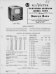
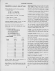
Specifications

SERVICE SUGGESTIONS
72 ITS
C
C
Some of the
possible
troubles that may be
encountered,
with
their effects and causes,
are listed
below:
NO
RASTER ON KINESCOPE—The
effect
of
no
raster can
be caused by
the following:
(1)
Incorrect
adjustment of ion trap
magnet.
(2)
No
high voltage.
Check V109 (6BG6-G) and
VI
10
(8016) tubes and
circuits. If the horizontal-deflection
circuits
are operating, as
evidenced
by
the correct
waveform measured
on
terminal 4 of horizontal output
transformer
T105,
the trouble
can be
isolated to the high-voltage
rectifier (VllO) circuit.
Either the high-voltage
winding (points 2 to 3 on T105) is open;
the 8016 tube is defective; its filament
circuit is open; or the
high-voltage filter capacitor C142 is
shorted.
(3)
Damper tube (VI 11, 5V4-G)
inoperative. Plate voltage
supply for 6BG6-G horizontal output tube is obtained
through
the damper tube. Check tube, and
heater winding on T106.
If tube is O.K.,
check
LI 13 (horizontal
linearity coil) for con-
tinuity, and capacitors C139 and
C140
for short
circuit.
(4)
Defective
kinescope. Heater open; cathode "return"
circuit open.
(5)
No plate voltage. Shorted electrolytic capacitor; open
speaker field coil. All -j-B measurements are accessible for
measurement
by removing cover from bleeder box.
(6)
Horizontal
osc. and control tube (V108, 6SN7-GT) in-
operative. Check
for sawtooth on
grid of horizontal
output
tube (V109. 6BG6-G). If not present, check waveforms,
volt-
ages, and components in V108 circuits.
HORIZONTAL
DEFLECTION ONLY—If horizontal deflection
only
is obtained, evidenced by
a
"straight line" across the
face of the kinescope, it
can be caused by the following:
(1)
Vertical oscillator
and output tube (V107, 8SN7-GT)
inoperative. Check waveforms
and
voltages
on grid and plate.
(2)
Vertical output transformer
(T103) open.
(3)
Yoke vertical coils
open.
POOR VERTICAL LINEARITY—
If
adjustment of the vertical
height
and linearity controls
will not correct this condition,
any of the following
may be
the
cause:
(1)
Vertical output transformer
(T103) defective.
(2)
Capacitors
C128-C or
C127-B
defective.
(3)
V107 (6SN7-GT)
defective.
Check
waveforms
and volt-
ages.
(4)
Excess leakage
or incorrect
value in capacitor
C130.
(5)
Low plate and bias
voltages. Check
rectifier tube
and
capacitors in
-|-B supply circuits.
(6)
Capacitor CI
29 defective.
POOR HORIZONTAL
LINEARITY
If adjustment
of controls
does not correct this
condition,
check the following:
(1)
Check or replace
horizontal output tube
(V109,
6BG6-G).
(2)
Check or
replace damper tube (VI
11, 5V4-G).
(3) Check waveform
on grid
of
V109.
(4)
Check linearity
coil L113 for
short circuit.
(5)
Check capacitors
C139
and C140 for defects.
TRAPEZOIDAL
OR
NON-SYMMETRICAL
RASTER
This
condi
lion
can
be caused by:
Defective
yoke.
WRINKLES
ON LEFT SIDE
OF RASTER
-This condition
can be
caused by;
Defective
yoke due to RlOl, H151.
or C141 (internal in yoke
assembly) being
wrong value or open. These
components are
mounted in rear of yoke assembly.
SMALL RASTER
This condition
can be caused by:
(1)
Low +B or line voltage.
(2)
Insufficient
output from horizontal output tube
Vi09
(6BG6-G).
Replace tube.
RASTER—
NO IMAGE, BUT ACCOMPANYING SOUND—This
condition
can be caused by:
(1)
No signal
on
kinescope grid. Check picture if amplifier
tubes VlOl (6AG5), V102 (6AG5). V103 (6AG5), second de-
tector V104 (6AL5), and' video amplifier V105 (12AU7).
(2)
Bad contact to kinescope grid. (Lead to
socket broken.)
SIGNAL APPEARS ON KINESCOPE
GRID BUT IMPOSSIBLE TO
SYNCHRONIZE
THE
PICTURE VERTICALLY
AND HORI-
ZONTALLY—
A
condition of this nature can be caused by:
(1)
Defective sync amplifier and
separator (V106, 6SN7-GT).
(2)
If tube is O.K., check
voltages, waveforms and
associated
circuits.
SIGNAL ON KINESCOPE GRID
AND
HORIZONTAL SYNC
ONLY
—
If this condition is
encountered, check:
Vertical integrating
network capacitors C164,
C123, C124,
C125,
and
resistors R13B, R137, R138.
PICTURE STABLE BUT
WITH POOR
RESOLUTION—If the
pic-
ture resolution
is
not up
to standard,
it may be
caused
by any
of the
following:
(1)
Defective
picture detector (V104,
6AL5) or
video amplifier
(V105, 12AU7).
(2)
Open video
peaking coil. Check
all
peaking
coils
(L104,
L105, L106,
L107)
for continuity.
Note that L105
and
LI 06 have
shunting
resistors.
(3)
Leakage
in V105
grid capacitor CI 15.
If above
components are
not found to
be
defective, check the
following:
(1)
Check all potentials
in video
circuits.
(2)
Check kinescope
grid circuit
for poor
or dirty
contact.
(3)
Check adjustment
of focus
control
(R129). It
should be
effective on either
side of proper
focus.
(4)
Check and
realign, if
necessary,
the picture
if and
r-f
circuits.
PICTURE
SMEAR—
(1)
Normally,
smear can be
attributed to
phase
shift at the
low-frequency
end of the
video
characteristic.
This can be
caused by
improper
values
of
R
and C
in the
video
circuits.
Check for
grid
current on
video
amplifier tube
V105.
(2)
This trouble
can
originate
in either
the
transmitter
or
the
receiver.
Check
reception
from
another
station.
PICTURE
JITTER—
(1)
1!
regular
sections at
the left
of the
picture
are
displaced,
replace the
horizontal
output tube (V109,
6BG6-G).
(2)
Vertical
instability may
be
due to
loose
connections
or
"noise"
received
with the
signal.
(3)
Horizontal
instability may
be
due
to
unstable
transmitted
sync, or
to "noise."