
Specifications

72 ITS
INSTALLATION INSTRUCTIONS
(Continued)
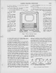
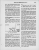
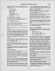
Figure 8
—R-F
Oscillator
Adjustments
VIDEO
PEAKING
LINK—A video
peaking
link is provided
to
permit
changing the video
response.
This link
is connected
at
the
factory with
the
peaking in.
However,
if
transients are
produced
on high
contrast
pictures the
peaking should be
taken out by
removing
the
link on the
terminal board
under
the chassis
near the
VI 04 socket. See
Figures 49
and 51
for
the
connection
and location
of the link.
ANTENNA TRAP
—
In some
sets, a
series resonant trap across
the
r-f amplifier
grid circuit is
provided to
eliminate
interference
from FM
stations on the
image of
channel
2,
from
interference
on
channel 6 from a
station on
channel 10 or
interference on
channel
5 from
a
station on
channel 7. In
production, this
trap is
adjusted to
reject the
channel
6-10'
interference. How-
ever, in the
field, it may be
necessary to
retouch the adjust-
ments
or to readjust
the trap
for channel
5-7
or
FM image
interference.
To
adjust the trap
in the
field, tune in the
station on which
the
interference is
observed. Tune
both cores
of the trap for
minimum
interference in
the picture. See
Figure 21 for the
location of the
trap. Keep both
cores
approximately the same
by
visual inspection.
Then, turn
one core V2 turn from the
original position
and repeak the
second for maximum rejec-
tion.
Repeat this process
until the best
rejection
is
obtained.
In severe
cases of such
interference, it may be
necessary to
reorient the antenna to
eliminate this
difficulty.
RECEIVER
LOCATION—The owner should be
advised
of
the
importance of placing the
receiver in the proper
location
in
the
room.
The location
shjDuld be chosen
—
—Away
from bright windows and so
that no bright light
will fall directly on the screen. {Some
illumination in the
room is
desirable, however.)
—To give easy
access for operation
and comfortable viewing.
—To
permit
convenient connection to
the antenna.
—
Convenient to an
electrical outlet.
—To
allow adequate
ventilation.
VENTILATION
CAUTION—
The
receiver is
provided with
adequate
ventilation holes in the
bottom
and back of the
cabinet. Care
should be taken not to
allow these
holes to
be
covered or
ventilation to be
impeded in any way.
ANTENNAS—The
finest television
receiver built
may
be said
to be
only as
good as the
antenna design
and installation. It
is
therefore
important to use a
correctly designed
antenna,
and
to use care
in its installation.
RCA
Television Antennas,
stock No. 225 and
No. 226, are de-
signed
for
reception on all thirteen
television channels.
These
antennas
use the
300-ohm RCA
"Bright Picture" television
transmission line.
Installation personnel are
cautioned not to
make
any changes in
the antenna or to
substitute other types
of transmission
line as
such changes may
result in unsatisfac-
tory
picture
reproduction.
The stock
#226
antenna is
bi-directional on
channels
one
through six
(44
to 88 Mc). When
used on these
channels, the
maximum
signal is obtained
when the antenna
rods are broad-
side
toward the transmitting
antenna.
The
stock
#225
antenna
with
reflector
is unidirectional
on
channels
one through six.
When used on these
channels, the
maximum
signal is obtained
when the antenna rods
are broad-
side toward
the transmitting antenna,
with the antenna
ele-
ment between the
reflector and the
transmitting
antenna.
When
operated on channels
seven through thirteen,
(174 to
216 Mc), both
types
of
antennas have
side lobes.
On
these
channels,
the maximum
signal will be obtained
when the
antenna
is rotated approximately
35 degrees in
either direc-
tion from its broadside
position toward
the
transmitting
an-
tenna.
In general,
the stock
#225
antenna
should
be
used
if re-
flections
are encountered,
if the signal strength
is weak, or if
the receiving location
is noisy. If
these conditions are not
en-
countered, the
stock
#226
antenna will probably
be satisfac-
tory.
In
some cases, the
antenna should not
be
installed
permanently
until the quality
of
the
picture reception has been
observed on
a
television
receiver.
A
temporary
transmission line
can be
run
between receiver and
the antenna, allowing sufficient
slack
to permit moving the
antenna. Then,
with a telephone
system connecting
an observer
at the receiver and
an assistant
at the antenna,
the antenna
can be positioned to give
the
most satisfactory
results on the received
signal. A shift of
direction
or a few feet
in antenna position
may effect a tre-
mendous
difference in picture reception.
REFLECTIONS
—Multiple
images sometimes known
as echoes
or ghosts, are
caused
by
the signal arriving
at the antenna
by two or more routes.
The second or
subsequent image
oc-
curs when a signal arrives
at the antenna after
being re-
flected off
a
building,
a hill or other object.
In severe cases
of reflections,
even the sound
may be distorted. In less
severe
cases, reflections
may occur that
are not noticeable
as re-
flections but that will
instead cause
a
loss
of definition in
the
picture.
Depending upon the circumstances,
it may
be
possible
to elim-
inate the
reflections
by
rotating
the
antenna
or by moving it
to a new location. In
extreme cases, it
may be impossible to
eliminate
the reflection.
Under
certain extremely unusual
conditions, it may
be
possible
to rotate
or
position
the antenna so that it
receives the cleanest
picture over a reflected path. If such
is the case, the antenna
should be so positioned. However,
such
a
position
may give
variable
results as the nature of reflecting
surfaces may vary
with weather conditions.
Wet
surfaces
have
been
known
to
have
different reflecting characteristics
than
dry surfaces.
INTERFERENCE
—Auto ignition, street cars,
electrical ma-
chinery and
diathermy apparatus
may cause
interference
which spoils the picture. Whenever
possible, the antenna
location should
be removed as far as possible from
highways,
hospitals, doctors' offices, and similar sources
of interference.
In mounting
the antenna, care must
be
taken
to
keep the
antenna rods at least Vi wave length
(at least 6 feet) away
from
other antennas, metal roofs, gutters, or other metal
objects.
Short-wave radio
transmitting and receiving equipment
may
cause interference in the picture
in
the
form of moving ripples.
In some instances
it may be possible to eliminate the inter-
ference
by the use of
a
trap in the antenna transmission line.
However, if
the
Interfering signal
is on the same frequency as
the
television
station,
a
trap will provide no improvement.
WEAK PICTURE
—When the installation is near the limit of the
area
served by the transmitting station, the picture
may be
speckled,
having
a
"snow" effect, and
may
not hold
steady on
the screen. This
condition is due to lack
of
signal strength
from the transmitter.
3