
Specifications

INSTALLATION
INSTRUCTIONS (Continued)
721TS
C
c
c
Slip the
kinescope
as
lar
forward as
possible. Slide
the
kinescope
cushion
firmly up
against the
flare of the tube
and
tighten the
adjustment
wing
screws. Slide
the
deflection
yoke as
far forward as
possible.
Connect the
high voltage
lead to
the
kinescope second anode
socket.
The antenna
and
power connections
should now be
made.
Turn the power
switch to the "on"
position,
the
brightness
control
fully clockwise, and
picture
control
counter-clockwise.
ION
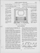
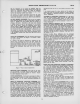
TRAP MAGNET ADJUSTMENT—The ion
trap rear magnet
poles
should
be
placed over
the ion
trap
flags
as shown in
Figure 4. Starting from this position
adjust
the
magnet
by
moving it lorward or
backward
at the same time
rotating
it
slightly around
the
neck of the kinescope for the brightest
raster on
the
screen. Reduce
the
brightness control setting
until the raster is slightly above average brilliance. Adjust
the focus control (R129
on the chassis rear apron) until the
line structure of the raster
is
clearly visible. Readjust the
ion
trap magnet for maximum raster brilliance. The final touches
on this adjustment should be made with
the
brightness control
at the maximum position with which good line focus
can be
maintained.
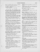
FOCUS COIL ADJUSTMENTS—
Turn the
centering controls R152
and R166 to
mid position. See Figure
7 for location
of these
rear apron controls.
If
a
corner of
the
raster is
shadowed, it
indicates that the
electron beam is
striking the neck of the tube.
Loosen the
focus coil
adjustment wing nuts
and rotate the coil
about its
vertical
and horizontal axes
until the entire raster is
visible,
approximately
centered and with no shadowed
corners. Tighten
the
focus coil adjustment wing nuts
with the
coil
in
this
position.
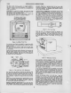
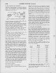
HOR.
LINEARITY
a.
RI48
VERT.
LINEARITY
FOCUS
q;^
WIDTH a
CONTROL
Ct36A
HOR. LOCKING^
(OX (CIX
HOR. DRIVE
«
*il>/VERT.
^CjpHOR.
CI36C e
CENTERING CENTERING
HOR.FREa.''
Figure
7
—
Rear Chassis
Adjustments
DEFLECTION
YOKE ADJUSTMENT—If the
lines of the raster
are not
horizontal or squared with
the picture mask, rotate
the deflection
yoke until
this
condition is obtained.
Tighten
the yoke
adjustment wing screw.
PICTURE ADJUSTMENTS—It
will
now be
necessary to obtain
a
test pattern
picture in order to make further adjustments. See
steps 2 through
9.
of the receiver
operating instructions
on
page 3.
CHECK OF
HORIZONTAL OSCILLATOR ALIGNMENT—Turn
the horizontal hold control to the extreme counter-clockwise
position. The picture should remain in
horizontal
sync. Mo-
mentarily remove the signal
by
switching
off channel and
then back. Normally
the
picture will
be out
of
sync.
Turn
the control clockwise slowly.
The number of diagonal bars
will be gradually reduced and
when only
3'/2
to
iVi
bars
sloping downward
to the left are obtained, the picture will pull
into sync
upon
slight
additional clockwise rotation of
the con-
trol. Pull in
should occur when the control
is approximately
90 degrees from the
extreme counterclockwise position.
The
picture
should remain
in sync for approximately
90 degrees
of additional
clockwise
rotation of the control.
At the
extreme
clockwise
position,
the picture should
be
out of sync and
should show from
3'/2
to
4'/2
bars sloping
downward
to the
right.
If the receiver passes the above checks and the picture is
normal and stable, the
horizontal oscillator is properly aligned.
Skip "Alignment of Horizontal Oscillator" and proceed
with
"Focus"
adjustment.
ALIGNMENT OF HORIZONTAL
OSCILLATOR—
If
in
the
above
check the receiver failed to
hold
sync
with the hold control
at
the extreme counterclockwise
position or failed to hold
sync at least 60 degrees
of clockwise rotation of the
control
from
the
pull in point, it
will
be
necessary to make the fol-
lowing adjustments.
Horizontal Frequency
Adiustment—Turn the
horizontal hold
control
to the
extreme clockwise
position.
Tune in
a
television
station
and adjust the rear
apron horizontal
frequency
trim-
mer C136C
until the picture is out
of sync and
shows 3Vi to
41/2
bars sloping
downward to the right.
If the
trimmer has
insufficient range, set the
trimmer to
mid-position
(1
turn
out
from max. capacity) and adjust the L121
horizontal frequency
adjustment
until
this
condition is
obtained. See
figure 22
for
the location of L121.
Horizontal Locking Range
Adjustment
—
Set the
horizontal
hold control to the
full counter-clockwise
position.
Momentarily
remove the signal
by
switching off
channel and, then
back.
Slowly turn the
horizontal
hold
control clockwise
and note
the
least
number
of diagonal bars
obtained just before the
picture
pulls
into sync.
If more than
4'/2
bars are present just
before the picture
pulls
into sync,
adjust
the
horizontal locking
range trimmer C136A
slightly clockwise. If less
than
3'/2
bars are
present, adjust
C136A
slightly counterclockwise. Turn the
horizontal hold
control counterclockwise,
momentarily remove the
signal and
recheck the number of bars present at the
pull in point.
Re-
peat this
procedure until 3V2 to
4'.^
bars are present.
Repeat
the
adjustments under
"Horizontal
Frequency
Adjust-
ment" and
"Horizontal
Locking
Range
Adjustment"
until the
conditions
specified
under
each are
fulfilled.
When
the
hori-
zontal hold
operates
as outlined
under
"Check of
Horizontal
Oscillator
Alignment"
the
oscillator
is
properly
adjusted.
HEIGHT
AND
VERTICAL
LINEARITY
ADJUSTMENTS—
Adjust
the
height
control (R141
on
chassis
rear apron)
until the
picture
fills
the
mask
vertically (6%
inches).
Adjust
vertical
linearity
(R148 on
rear
apron),
until the
test
pattern
is
symmetrical
from
top to
bottom.
Adjustment
of
either
control will
require a
read-
justment of the
other.
Adjust
vertical
centering
to
align the
picture
with the
mask.
WIDTH.
DRIVE
AND
HORIZONTAL
LINEARITY
ADJUSTMENTS
—Turn
the
width
control
LI 12 to
the
maximum
clockwise
posi-
tion.
Vary the
horizontal
drive
trimmer
C136B
to
yield
the
best
compromise
between
brightness and
linearity.
Adjust
the
horizontal
linearity
control
LI 13
for
best
linearity
of
the
right half
of the
picture.
Readjust
the
width
control
until the
picture
just fills
the
mask.
Adjust
horizontal
centering
to
align the
picture
with the
mask.
FOCUS—
Adjust
the
focus
control
R129
for
maximum
definition
of the
vertical
wedge
of the
test
pattern.
Check
to see
that
all
cushion,
yoke,
focus
coil
and
ion trap
magnet
thumb
screws
are
light.
Replace
the
cabinet
back
grille.
Make
sure
that the
back is
on
tight,
otherwise
it may
rattle at
high
volume.
CHECK
OF
R-F
OSCILLATOR
ADJUSTMENTS—
With a
crystal
calibrated
test
oscillator
or
heterodyne
frequency
meter,
check
to
see
if the
receiver
r-f
oscillator
is
adjusted
to
the
proper
frequency on
all
channels.
If
adjustments
are
required,
these
should be
made by
the
method
outlined
in
the
alignment
pro-
cedure on
page
10. The
adjustments
for
channels
1
through 5
and
7
through
12
are
available
from
the
front of
the
cabinet
by
removing
the
station
selector
escutcheon
as
shown
in
Figure
8.
Adjustments
for
channels
6
and
13
are
under
the
chassis.
Tune
in all
available
Television
Stations,
Observe
the
picture
for
detail,
for
proper
interlacing
and
for
the
presence
of
interference
or
reflections.
If
these
are
encountered,
see
the
section
on
antennas
on
page
6.