
Specifications
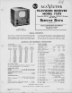

721TS
INSTALLATION
INSTRUCTIONS
The
Model 72 ITS television receiver
is shipped
complete in
one carton except
for
the
10BP4
kinescope. The kinescope
is
shipped in
a
special carton and should not
be unpacked until
ready ior installation.
UNPACKING—To unpack the receiver,
tear open the carton
flaps,
pick the receiver
up
from under
the bottom of the cab-
inet and
lift
it
out of
the shipping carton.
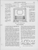
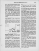
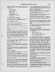
Take the metal grill off the back of the
cabinet.
Remove
the
front panel from the cabinet as indicated in Figure
3.
TO
REMOVE CABINET
FRONT
TAKE
OUT
SCREWS UNDER
CABINET
LOOSEN WING NUTS
INSIDE
CABINET
TURN PLATES
AND
REMOVE
FRONT
Figure
3
—
Cabinet, Front View
The operating
control knobs
are packed in
a
paper bag which
is tied to the
focus coil mounting
bracket inside the cabinet.
Remove the bag.
Remove
the
protective
cardboard shield from the
5U4G recti-
fier. Make sure
all tubes are in place
and are firmly seated
in
their sockets.
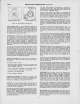
Loosen the
two kinescope
cushion adjustment wing
screws and
slide the
cushion toward the rear
of
the
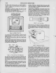
chassis. Loosen the
deflection yoke
adjustment, slide the yoke
toward the rear
of the
chassis and tighten.
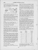
See
Figure
4
for the location
of
the
cushion and yoke
adjustments.
/
FLAGS
Ml
FRONT
MACNET
GAP
ON THIS SIDE AND
EVEN
WITH REAR
MAGNET
GA»
Figure
4
—
Yoke and Focus Coil Adjustments
From
the
front of the cabinet, look through
the deflection
yoke
and check the alignment of the focus coil
with the yoke. If
the focus
coil
is not in line, loosen the three focus coil
adjust-
ment wingnuts and raise, lower, or rotate the
coil until align-
ment
is
obtained. Tighten the
wingnuts with the coil in
this
position.
Loosen the two lower kinescope face centering slides, and
set
them at approximately mid position.
See
Figure
3 for loca-
tion of the slides and their adjustment
screws. Loosen
the
ion trap magnet adjustment
thumb screws.
KINESCOPE HANDLING
PRECAUTION—
Do not open the kine-
scope
shipping carton, install, remove, or handle
the kinescope
in
any manner, unless shatterproof goggles
and heavy
gloves
are worn.
People not so
equipped
should
be kept
away
while
handling the
kinescope.
Keep
the kinescope
away from the
body while
handling.
The
shipping
carton
should
be kept
for
use in
case
of future
moves.
INSTALLATION
OF
KINESCOPE—
The kinescope
second
anode
contact
is
a
recessed
metal
well in
the side
of
the bulb.
The
tube
must
be installed
so that
this
contact
is
approximately
on
lop.
The
final
orientation
of
the tube
will
be determined
by
the
position
of the
ion trap
flags.
Looking
at the
kinescope
gun
structure,
it will
be observed
that
the
second
cylinder
from
the
base inside
the
glass
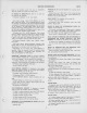
neck
is provided
with
two
small
metal
flags,
as shown
in
Figure
5. The
kinescope
must
be
installed
so
that
when looking
down
on the
chassis,
the
two
flags
will
be seen
as shown
in
Figure
4.
T
FLAGS
"S'3^
Figure
5
—
Ion
Trap
Flags
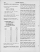
Insert
the
neck
of
the
kinescope
through
the
deflection
and
focus
coils
as
shown
in
Figure
6
until
the
base
of
the
tube
protrudes
approximately
two
inches
beyond
the
focus
coil.
If the
tube
sticks,
or
fails
to
slip
into
place
smoothly,
investi-
gate
and
remove
the
cause
of the
trouble.
Do
not
force
the
tube.
Figure
6
—
Kinescope
Insertion
Early
production
receivers
employed
an
EM type
of
ion
trap
magnet
like
that in
the model
630TS
receiver.
Late
production
receivers
employed
a PM type
magnet
as shown
in
Figure
4.
If
an EM
type
of magnet
is
applied,
slip
the
assembly
over
the neck
of
the
kinescope
with
the
coils
down
and the
large
coil
towards
the
base of
the
tube.
Tighten
the
magnet
ad-
justment
thumbscrews
sufficiently
to hold
it in
position
but still
free
enough
to
permit
adjustment.
If
the
PM type
is
employed,
slip
the
assembly
over
the neck
of
the kinescope
with
the large
magnet
towards
the
base of
the
tube
and
with the
arrow
on the
assembly
up
as shown
in
Figure
4. The front
magnet
is
movable
on the
assembly.
The
correct
position
of the front
magnet
is with
the
gap on the
left
side (from
the
rear of
the
cabinet)
and even
with
the
gap
of
the
rear
magnet.
Connect
the kinescope
socket
to the
tube
base. Insert
the
kinescope
until
the face
of
the tube
protrudes
approximately
one-eighth
of an
inch outside
the front
of
the cabinet.
Adjust
the four
centering
slides
until
the face
of the
kinescope
is in
the
center of
the
cabinet
opening.
Tighten
the four
slides
securely.
Wipe
the kinescope
screen
surface
and front
panel
safety glass
clean
of all
dust
and finger
marks
with
a
soft cloth
moistened
with the
Drackett
Co.'s "Windex"
or similar cleaning
agent. Install
the
cabinet front
panel
by reversal
of
the remov-
ing process
as
shown
in Figure
3. Install
the
control knobs
on the
proper
control shafts.
3-