
Specifications

RECEIVER
OPERATING
INSTRUCTIONS
72 ITS
The
following
adjustments are necessary when
turning the
receiver on ior the
first time:
1. Turn the
receiver "ON" and
advance the
SOUND
volume control to
approximately mid-position.
2. Set
the STATION
SELECTOR to the desired channel.
3. Turn the
PICTURE
control
fully counter-
clockwise.
4.
Turn the
BRIGHT-
NESS
control fully coun-
terclockwise,
then clock-
wise until
a
faint glow
just
appears on the
screen.
5.
Turn the
PICTURE
control
approximately
three-fourths
clockwise.
6.
Adjust the
FINE
TUNING
control for
best
sound
fidelity
and the
SOUND
control for
suit-
able
volume.
7.
Adjust the
VERTI-
CAL
hold
control
until
the
pattern
stops
vertical
movement.
PICTURE
BRIGHTNESS
8.
Adjust the
HORIZONTAL
hold control
until
the
picture
appears on the
screen.
9.
Adjust the
PICTURE control
for suitable
picture
contrast.
10. After
the receiver
has been on
for some time,
it
may
be
necessary to
readjust the
FINE
TUNING
control slightly for
improved sound
fidelity.
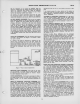
.^^=^
\==J^
ON-OFF
SOUND'
I
FINE TUNING
STATION
SELECTOR
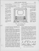
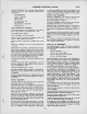
IN SOME
RECEIVERS "BRIGHTNESS" IS
THE OUTER
KNOB AND
'PICTURE'
THE INNER
Fig/iie I
—
Receiver
Operating
Controls
CIRCUIT
DESCRIPTION
11. In
switching from
one
station to
another,
it may be
necessary
to
repeat steps
number 6
and 9.
12.
When the set
is
turned on again
after an
idle
period, it
should not
be
necessary to
repeat
the
adjustments if the
positions of the
controls
have
not been
changed.
If
any
adjustment is
necessary, step
number
6 is
generally
sufficient.
13. If the
positions of
the
controls have
been
changed, it may be
nec-
essary to
repeat
steps
number 1 through 9.
c
The
general design
features
of the
721TS
television
receiver
are
conventional.
However, the
a-f-c
horizontal
hold
circuit
is
new
and
will be
described
briefly.
Fundamentally
the
horizontal
oscillator is
a
free
running block-
ing
oscillator
and
discharge
circuit.
The
incoming
sync
is
superimposed
on the
horizontal
oscillator
waveform
and ap-
plied to the
control tube
grid.
If the two
voltages
are not
in
the
proper
freguency
and
phase
relations, the
control
tube ap-
plies a
bias to
the
oscillator to
bring it
into
sync.
A
portion
of the
bias
from the
blocking
oscillator
is
applied
to the grid
of the
control
tube
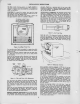
and is
sufficient
to keep
the
control
tube cut
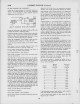
off except
when the
sync
pulse is
high
on
the slope
of the
grid
waveform
as
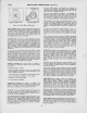
shown in
Figure 2-A.
If the
oscillator
changes
phase so
that the
pulse
slides down
the
slope, the
plate
conduction
time
decreases as
shown in
Figure
2-B. If the
pulse
slides up
the
slope, then
the
plate
conduction time
increases as
shown in
Figure 2-C.
When the
control
tube
conducts
capacitors
C16I and
CI67
in
its
cathode
circuit
charge
to
a
d-c
potential
proportional
to
the
plate
conduction
time.
This
potential is
applied
as
a
bias
to
the
oscillator
grid thus
shifting
the
oscillator
frequency
and
pulling it
into
phase with
the sync
pulses.
The
effect of the
various
controls
associated
with the
circuit
are
as follows.
LI2I
is tuned
with a
slug to
effect
coarse
adjustments
in
oscillator
frequency.
C136C
is
provided
to
effect
fine
adjustments
in
frequency.
RI56 the
horizontal
hold
control is
provided on the
front
panel to
permit
a
5%
variation
of
frequency by
varying the
control tube
plate
volt-
age.
CI 36
A is
a
variable
portion of a
capacity
voltage
divider
and
is
provided to set
the
amplitude
of the
waveform
on
the
grid of the
control lube
so that
conduction
occurs only
on the
positive
peaks
of the
waveform.
The
horizontal
drive
control
C136B is
part of a
capacity
voltage
divider and
is
pro-
vided to
vary the
amount of
sawtooth
voltage on
the
VI 09
grid
and hence
is a
control
for
picture
linearity.
Several
components
of the
oscillator
and
control
circuits
have
special
coefficients
or
characteristics
and in
case
of
failure,
should be
replaced
only by
exact
replacement.
RI73
is a
special
resistor
capable
of
stability
of
1%
or
better.
R191
is a
high
negative
coefficient
resistor
to
compensate
for
warm up
drift.
It is
mounted
within about
Vi
inch of
the
power
transformer
and
chassis
for
good
heat
transfer. The
dress of
this
component
should
not be
disturbed.
Strains or
excessive
heat
should
not be
applied to
the
leads
or
bodies
of the
resistors
associated
with the
horizontal
oscillator
and
control
circuits.
Such
conditions
may
cause
excessive
changes
of
resistance
with age.
See
"Critical
Lead
Dress"
on
page
18.
VIOBA
GRID CUTOFF
NORMAL CONTROL
SYNC
TOO LATE
SYNC TOO
EARLY
SHADED
AREA IS
PORTION OF
W/AVEFORM
EFFECTIVE
IN
PRODUCING
OSCILLATOR
CONTROL
VOLTAGE,
Figure 2
—
Horizontal
Control
Waveforms