
Specifications

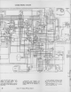

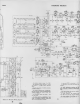
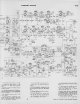


SCHEMATIC
DIAGRAM
721TS
VI
14
6bA6
15T.
SOUND 1-F
AM
resistance values
in ohms. K
:
1000.
All
capacitance values
less than
1 in MF
and
above 1 in
MMF unless otherwise
noted.
Direction
of arrows
at
controls
indicates
clockwise
rotation.
All voltages measured
with "VoltOhmyst"
and with
picture control counterclockwise.
Voltages
should hold within
±20% with
I
1 7 v. a-c supply.
Coil resistance values
less than 1 ohm
ore not shown.
In some receivers,
substitutions
hove
caused changes
in component
lead color
codes,
in electrolytic capacitor
values and
their
lug identification
markings.
In some
sets R108 is connected to ~!4V.
In some
sets L122, R195 and R193 are
omitted.
In early production
receivers an
EM
type of ion trap
magnet was employed and
was
connected
as shown by the dotted
lines.
R195 was omitted in receivers employ-
ing
an EM type magnet.
In some
receivers,
the
antenna
trap
(L81, L82,
C21
and
C22) may be omitted.
In
some receivers,
the bottom end of
CI 42 is connected to
pin 4 of VII
1.
21
In some receivers,
a
single coil,
L102, is
used
in place of
T104.
LI
02 is
tuned to
26 mc.
In early production
receivers
the
resist-
ance
of the focus coil was 247 ohms.
R197 was
employed only in receivers
with
the 247-ohm focus coil.
Optional
video peaking Is provided
by
the video peaking
link. Normally the link
is connected
in place. However, if tran-
sients are produced
on high
contrast
pic-
tures,
the link should be opened. See fig-
ure 49 for
location
of the link.
In
some receivers, R-149 is 3300 ohms.
Figure 51
—
Overall Circuit Schematic Diagram