
Specifications


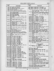


72 ITS
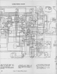
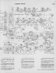
SCHEMATIC
DIAGRAM
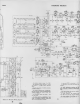
Figure
50
—
jR-F Unit Wiring
Diagram
20
I n some receivers, substitutions have
caused changes
In
component
lead
color
codas,
in
electrolytic
capacitor values and
their lug identification
markings.
In early production receivers Qr\ EM
type of ion trap magnet was
employed
and
was connected as shown by the dotted
ines.
R196 was
omitted
in
receivers employ-
ng
an EM type magnet.
In some receivers, the
antenna trap
(LSI,
L82, C21
and
C22)
may be
omitted.
In some receivers, the bottom end of
CH2 is connected to pin 4 of Vlll
21