
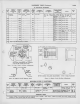
Specifications


ALIGNMENT
PROCEDURE
(Continued)
72 ITS
c
c
Connect the
signal
generator to the
receiver antenna
terminals.
The
order of
alignment
remains
the
same
regardless of
which
method
is used.
Since lower
frequencies
are obtained by
adding
steps of
inductance,
it is
necessary to align
channel 13
first and con-
tinue in
reverse numerical
order.
Set the
receiver
channel switch to
channel 13.
Adjust the frequency
standard to
the correct
frequency (237
mc. for
heterodyne frequency
meter or 215.75 mc.
for the
signal
generator).
Set the fine
tuning control to the
middle of its range
while mak-
ing
the adjustment.
Adjust
L77
and L78 for an
audible beat on the
heterodyne
frequency meter or
zero voltage from sound
discriminator. The
core stud
extensions should be
maintained equal by
visual
inspection.
Switch the receiver to
channel 12.
Set the
frequency standard to the
proper frequency as
listed
in
the
alignment table.
Adjust L76
for indications as above.
Adjust the oscillator to frequency on all
channels by switch-
ing the receiver and the
frequency standard to each
channel
and
adjusting the appropriate
oscillator trimmer for the
speci-
fied indication. It should be
possible to adjust the
oscillator
to the correct
frequency on all channels with the fine
tuning
control in
the
middle third of its range.
After
the oscillator has been set on all channels, start back
at
channel 13 and recheck to make sure that
all adjustments are
correct.
RETOUCHING
OF
PICTURE
I-F
ADJUSTMENTS—
The picture i-f response curve
varies
somewhat
with change
of bias and for this reason it should be
aligned with approxi-
mately the same
signal input as it will receive in
operation.
If the receiver is located at the edge of the
service area, it
should be aligned
with approximately
—1
volt i-f grid bias.
However, for normal conditions, (signals of 1000
microvolts
or greater), it is recommended that the picture i-f be aligned
with
a
grid bias of
—3
volts. Set
the picture control for
—3
volts
at the
junction of R106 and R107.
Connect the
r-f sweep generator to the receiver antenna ter-
minals.
Connect the signal generator to the antenna terminals and
feed in the 25.75 mc. if picture carrier marker and
a
23 mc.
marker.
Connect the oscilloscope across the picture detector load re-
sistor, R118.
Set
the channel switch to channel (between 1 and
6)
found
to have the best response during the r-f and converter
line ad-
justment.
Set the sweep output to produce
approximately .3 volt peak-to-
peak across the picture detector load resistor.
Observe and analyze the response curve
obtained. The re-
sponse will not
be
ideal and the i-f
adjustments must
be
retouched in order to obtain
the
desired curve. In
making
these adjustments, care should
be
taken that no two
trans-
formers are tuned to the same frequency as i-f
oscillation
may
result.
On final adjustment
the picture carrier
marker
must be at
approximately 45% response. The curve must be
approxi-
mately flat topped and with
the 23 mc. marker at approxi-
mately 90% response.
The
most important consideration in
making the i-f adjust-
ments is to get the picture
carrier at the 45% response
point.
If the picture carrier
operates too low on the
response curve,
loss of low
frequency video response,
of picture brilliance,
of
blanking, and of sync may occur.
If the picture carrier
oper-
ates too high on the
response curve, the picture
definition is
impaired by
loss of
high
frequency video
response.
SENSITIVITY CHECK—A
comparative sensitivity
check can be
made
by
operating the
receiver on a
weak signal from
a
television station and
comparing
the
picture and sound ob-
tained to that obtained on
other receivers under the
same
conditions.
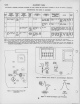
This weak signal can be
obtained by
connecting the shop
antenna to the
receiver through
an attenuator pad
of
the type
shown
in Figure 10. The
number of stages
in the
pad de-
pends upon the
signal strength
available at the antenna. A
sufficient number of
stages should be
inserted so that
a
some-
what less
than normal contrast
picture is obtained when the
picture
control is at the
maximum
clockwise position.
1ZO
-vww-
.^vvvvv-
I20
^
RECEIVER
I
ANTENNA
I
TERMINALS
-vww-
-WWAr-
-JWSA/V-
Vigure
10
—
Attenuator
Pad
Only
carbon
type
resistors
should be
used
to
construct the
attenuator
pad.
Since
many
of the
low value
moulded
re-
sistors
generally
available
are
of wire
wound
construction,
it is
advisable to
break
and
examine one
of
each type
of re-
sistor
used in
order to
determine its
construction.
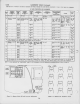
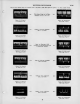
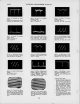
RESPONSE
CURVES
—The
response
curves
shown on
pages
12,
14 and
15
and
referred to
throughout
the
alignment
pro-
cedure
were
taken
from a
production
set.
Although
these
curves
are
typical, some
variations
can be
expected. Chan-
nel
2 r-f
response (not
shown)
is
similar
to that
of
channel 3.
The
response
curves are
shown
in the
classical
manner
of
presentation, that
is
with
"response up"
and
low
frequency
to
the
left. The
manner
in
which they
will be
seen in a
given
test
set-up
will
depend
upon the
characteristics
of
the
oscillo-
scope
and the
sweep
generator.
The
curves may
be
seen in-
verted
and /or
switched
from
left to right
depending
on the de-
flection
polarity of the
oscilloscope
and
the
phasing
of the
sweep
generator.
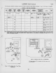
ALIGNMENT
TABLE—Both
methods of
oscillator
alignment
are
presented in
the
alignment
table. The
service
technician may
thereby
choose the
method
to
suit his
test
equipment.
If it
is
found that the
dual
listing
is
confusing, the
unwanted
listing
can be
easily
erased.
11