
Specifications

721TS
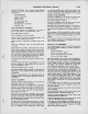
ALIGNMENT PROCEDURE (Continued)
H-F AND
CONVERTER LINE
ADJUSTMENT—
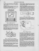
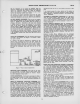
Connect the
r-f sweep
oscillator
to the
receiver antenna
ter-
minals. If the
sweep
oscillator has a 50
ohm
single-ended
output, it
will be
necessary to
obtain balanced
output by
connecting
as shown in
Figure 9.
D
IZO
A.
—
(/VA/"
—
BO OUM
UNBALANCED
SWEEP OUTPUT
CABLE
MSa2T
RECEIVER
ANTENNA
TERMINALS
<S)
db
figure 9
—
Unbalanced Sweep
Cable
Termination
Connect
the
oscilloscope to the
junction
of
C14
and
R6 (in the
r-f tuning
unit)
through
a
10,000
ohm
resistor.
By-pass the
first
picture if grid to
ground through a
1000
mmfd.
capacitor.
Keep
the leads to
this by-pass as
short as
possible.
If
this is not
done, lead
resonance may
fall in the
r-f range
and cause an
incorrect
picture of the
r-f response.
Connect the
"VoltOhmyst" to
the
junction of R170
and R171
and
adjust the
picture
control for
-1
volt on
the meter.
Connect the
signal
generator
loosely
to the receiver
antenna
terminals.
Since
channel 7
has the
narrowest
response of any
of
the
high
frequency
channels,
it should be
adjusted first.
Set
the
receiver
channel switch
to channel 7
(see Figure 18
for switch
shaft
flat
location versus
channel).
Set
the sweep
oscillator to
cover channel 7.
Insert markers
of channel
7 picture
carrier and sound
carrier
175.25 mc.
and
179.75 mc.
Adjust
L25, L26,
L51 and L52
(see Figure
16)
for an approxi-
mately
flat topped
response
curve located
symmetrically be-
tween the
markers.
Normally
this curve appears
somewhat
overcoupled or
double humped
with
a
10 or 15%
peak to val-
ley
excursion and
the markers
occur at
approximately
90%
re-
sponse. See
Figure 17,
channel 7.
In making these
adjust-
ments, the
stud
extension of all cores
should be
kept approxi-
mately
equal.
Check the
response
of channels 8
through 13
by
switching
the
receiver
channel
switch, sweep
oscillator and marker
oscillator to each
of these
channels and
observe the response
obtained. See
Figure
17 for typical
response curves. It
should
be found
that all
these channels
have the proper shaped re-
sponse
with the
markers above
70% response.
If
the
markers
do
not fall
within this
requirement on one
or more high fre-
quency
channels,
since there are no
individual channel ad-
justments, it
will
be
necessary to
readjust L25, L26, LSI and
L52, and
possibly
^compromise some channel
slightly in order
to
get the
markers up on
other channels. Normally however,
no
difficulty of this type
should
be
experienced since the
higher frequency
channels become
comparatively broad and
the
markers
easily fall
within
the
required range.
Channel
6 is next
aligned
in
the same manner.
Set
the receiver to
channel 6.
Set the sweep
oscillator to cover
channel 6.
Set the marker
oscillator
to
channel 6 picture and
sound car-
rier frequencies.
Adjust Lll,
LI2, L37 and
L38, for
an approximately
flat-topped
response curve
located symmetrically
between
the
markers.
Check
channels
5 down through
channel 1
by switching
the
receiver,
sweep oscillator
and marker oscillator
to
each chan-
nel and observing
the response
obtained. In
all cases,
the
markers should
be above the 70%
response
point. If
this is
not
the case, Lll, L12,
L37 and L38
should
be
retouched.
On
final adjustment,
all channels
must be within
the 70%
spec-
ification.
Coupling
between r-f and
converter lines is
augmented
by
a
link
between L12 and L37. This
link is
adjusted in
the
factory and should
not require adjustment
in the field.
On
channel 6 with the link in
the minimum coupling
position,
the
response is slightly
overcoupled with
approximately
a
10%
excursion from peak-to-valley.
With the
coupling at maximum,
the response is somewhat broader
and the
peak-to-valley
ex-
cursion is approximately
40%. The amount
of coupling
per-
missible is
limited by the peak-to-valley
excursion
which
should
not be greater
than 30 °o on any
channel.
Remove the
1000
mmf capacitor
from the first
picture i-f
grid.
R-F OSCILLATOR LINE
ADJUSTMENT—
The
r-f oscillator line
may be aligned by adjusting
it to beat
with
a
crystal calibrated
heterodyne frequency meter,
or by
feeding
a
signal into the receiver
at the r-f sound carrier
fre-
quency and
adjusting
the oscillator for zero output
from
the
sound discriminator. In this latter
case
the
sound discriminator
must first have been aligned to exact frequency.
Either method
of adjustment will produce
the same results. The method
used
will depend upon the
type
of
test
equipment
available.
Regardless of which method of oscillator alignment
is used,
the frequency standard must
be
crystal controlled
or
calibrated.
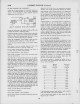
If the receiver oscillator is to be adjusted
by
the heterodyne
frequency meter
method, the frequencies listed
under "R-F
Osc.
Freq." in the table must be available.
If the
receiver oscillator is adjusted by feeding in the r-f
sound
carrier signal, the frequencies
listed
under "R-F Sound
Carrier" must be available.
Receiver R-F Sound
Channel R-F
Osc. Carrier
Number Freq. Mc.
Freq. Mc.
1
71
49.75
2
81
59.75
3
87
65.75
4
93
71.75
5
103
81.75
6
109
87.75
7
201
179.75
8
207
185.75
9
213
191.75
10
219
197.75
II
225
203.75
12
231
209.75
13
237
215.75
If the
heterodyne
frequency
meter
method
is used,
couple the
meter probe
loosely to
the
receiver
oscillator.
If the
r-f sound
carrier
method
is used,
connect
the
"Volt-
Ohmyst" to
pin 1 of
V116.
3
10