SpeedTouch™ (Wireless) Business DSL Router IPQoS Configuration Guide Release R5.3.
SpeedTouch™ IPQoS Configuration Guide R5.3.
Copyright Copyright ©1999-2005 THOMSON. All rights reserved. Passing on, and copying of this document, use and communication of its contents is not permitted without written authorization from THOMSON. The content of this document is furnished for informational use only, may be subject to change without notice, and should not be construed as a commitment by THOMSON. THOMSON assumes no responsibility or liability for any errors or inaccuracies that may appear in this document.
Contents Contents About this IPQoS Configuration Guide...................... 7 E-NIT-CTC-20041213-0013 v0.5 1 Document scope ........................................................... 9 2 Introduction ................................................................. 11 2.1 What is Quality of Service? .......................................................... 12 2.2 Relative versus Guaranteed QoS.................................................. 14 3 Basic QoS Concepts..........................
Contents 4 5.1 Classification ............................................................................... 30 5.1.1 Order of classification rules............................................................................ 31 5.2 Labels ........................................................................................... 33 5.2.1 Label parameters explained ............................................................................ 35 5.2.2 Using TOS, DSCP or Precedence ..................
Contents E-NIT-CTC-20041213-0013 v0.5 7.1 Configuring labels and rules for VoIP. ......................................... 86 7.2 Configuring labels and rules for DSCP. ....................................... 90 7.3 Configuring labels and rules for Interactive traffic. .................... 92 7.4 IPQoS configuration..................................................................... 95 8 Scenario 2: Business user with TOS marking. ......... 97 8.1 Labels .......................................
Contents
About this IPQoS Configuration Guide About this IPQoS Configuration Guide In this configuration guide This routing configuration guide explains how routes can/must be used in SpeedTouch™ R5.3 products. To explain the use of routes, a distinction is made between standard IP forwarding and packet-based classification. All examples start from a clean SpeedTouch™ configuration. Used Symbols A note provides additional information about a topic.
About this IPQoS Configuration Guide 8 E-NIT-CTC-20041213-0013 v0.
Chapter 1 Document scope 1 Document scope Introduction E-NIT-CTC-20041213-0013 v0.5 The SpeedTouch™ Release 5.3.0 has a strong Quality of Service (QoS) base that allows classification and forwarding of data to a single or multiple ATM VPI/VCIs with each a set of ATMQoS parameters. IP Quality of Service is an extension to this QoS framework.
Chapter 1 Document scope
Chapter 2 Introduction 2 Introduction Introduction This chapter gives a general description and use of Quality of Service. In this chapter Topic E-NIT-CTC-20041213-0013 v0.5 Page 2.1 What is Quality of Service? 12 2.
Chapter 2 Introduction 2.1 What is Quality of Service? Definition Quality of Service is the ability for an application to obtain the network service it requires for successful operation. Nowadays the total amount of data traffic increases, while new types of data emerge, like: voice data, video data, audio data. These new types of data pose new requirements for data transport, e.g.
Chapter 2 Introduction Bandwidth versus QoS Quality of Service is really best noticed when the Best Effort service encounters congestion. So a common question is "why not provide more bandwidth, use Best Effort, and get rid of complicated QoS architectures?" There are four answers: First of all, it is less economic to use more bandwidth than to use QoS. Many congestion problems can be resolved by using QoS. The second reason is, Denial of Service (DoS) attacks can always fill links.
Chapter 2 Introduction 2.2 Relative versus Guaranteed QoS Types of QoS There are two different approaches to achieve QoS: Guaranteed QoS: Measurable connection parameters are specified for certain data or for a connection, for example a guaranteed amount of bandwidth or delay across the network. This allows for an exact specification and measurement of the Quality of Service of data or a connection.
Chapter 3 Basic QoS Concepts 3 Basic QoS Concepts Introduction This chapter provides a brief explanation about: Basic concepts of Quality of Service in general. Precedence and TOS in general The Differentiated Services architecture in detail In this chapter Topic E-NIT-CTC-20041213-0013 v0.5 Page 3.1 Precedence and TOS 16 3.2 Differentiated Services 18 3.3 Classification and conditioning principles 20 3.
Chapter 3 Basic QoS Concepts 3.1 Precedence and TOS Introduction There are two generations of quality of service architectures in the Internet Protocol. The interpretation of the Type of Service Octet in the Internet Protocol header varies between these two generations. The figure below shows the Internet Protocol header. The Type of Service Octet is the second 8-bit octet of the Internet Protocol header.
Chapter 3 Basic QoS Concepts Precedence values The table below gives the precedence values: Precedence Purpose 0 Routine 1 Priority 2 Immediate 3 Flash 4 Flash Override 5 CRITIC/ECP 6 Internetwork Control 7 Network Control Note that IP Precedence is obsolete and is only implemented to provide backwards compatibility. Second generation The Differentiated Service Code Point is a selector for router's per-hop behaviours.
Chapter 3 Basic QoS Concepts 3.2 Differentiated Services Introduction Differentiated Services (DiffServ) is an architecture which allows service providers to offer different kinds of services to different customers and their traffic streams. Differentiated Services is a framework for scalable service discrimination and allows an approach to modular IPQoS objectives for the needs of various types of applications.
Chapter 3 Basic QoS Concepts Differentiated Services domain A DiffServ domain consists of a set of DiffServ nodes which can provide the common service and which have a set of PHBs implemented on each node. The DiffServ domain has two types of nodes: boundary nodes at the edges of the domain interior nodes inside of the domain. The boundary nodes are the access routers and edge routers that directly peer with customers (either individual users or other ISPs).
Chapter 3 Basic QoS Concepts 3.3 Classification and conditioning principles Introduction Packets go through a number of phases as they transit the network: classification, marking, shaping, policing and queuing. These phases can occur a number of times at each QoS-aware router in the path of the packet. For example, a host might mark outgoing traffic as "best effort", "scavenger", "discard at edge" or "discard at paid link".
Chapter 3 Basic QoS Concepts Marking Once classified, a packet is marked to avoid repeated re-classifications. The marking is made to the Differentiated Services Code Point (DSCP). The DSCP is trusted by later routers, so that the high cost of classifying traffic occurs only once. Shaping At the outgoing network edge, traffic is shaped to meet the traffic contract. Metering Policing E-NIT-CTC-20041213-0013 v0.5 At the outgoing network edge, traffic is metered to meet the traffic profile.
Chapter 3 Basic QoS Concepts 3.4 Differentiated Services Code Point (DSCP) Introduction A small bit-pattern, called the DS field, in each IP packet is used to mark the packets that should receive a particular forwarding treatment. The DS field uses the space of the former ToS byte in the IPv4 IP header and the traffic class byte in the IPv6 header. All network traffic inside of a domain receives a service that depends on the traffic class that is specified in the DS field.
Chapter 3 Basic QoS Concepts E-NIT-CTC-20041213-0013 v0.
Chapter 3 Basic QoS Concepts Assured Forwarding (AF) PHB Group: The Assured Forwarding (AF) PHB group allows a provider to offer different levels of forwarding assurances for IP packets. The delivery of IP packets is provided in four independently forwarded AF classes (AF1x through AF4x). Each AF class is allocated a certain amount of forwarding resources (buffer space and bandwidth) in a DS node.
Chapter 4 IP QoS Framework Overview 4 IP QoS Framework Overview Introduction This chapter presents an overview of the main components of the IP QoS framework within the SpeedTouch™. In this chapter Topic E-NIT-CTC-20041213-0013 v0.5 Page 4.1 Main Framework Components 26 4.
Chapter 4 IP QoS Framework Overview 4.1 Main Framework Components Graphical overview The figure below shows a graphical overview of the main components in the upstream datapath.Notice that there are two main blocks, the input and output. In between these two blocks the IP packets go through a series of processes like firewall, nat etc.
Chapter 4 IP QoS Framework Overview 4.2 Resource Management Introduction The RM module reserves memory for four independent traffic classes. Resources are reserved for each RM-class, both in the upstream and in the downstream direction (8 reservations in total). The figure below shows the Resource Management reservations.
Chapter 4 IP QoS Framework Overview Mapping to internal class The RM module maps packets to the an internal class depending on ATM QoS, VLAN priority or DSCP settings. The table below shows the relation between these settings. Once the mapping to the internal classes has been completed the packet goes through a number of processes like firewall, nat etc. Finally once the packet is ready for output it will be put in one of the 6 queues based upon its internal class.
Chapter 5 Packet Classification and Labelling 5 Packet Classification and Labelling Introduction This chapter will explain in detail how packets are classified. This classification is configured via rules in a packet filter mechanism. When a packet hits a rule, it will be marked with the label that is associated with this rule. Like this, packets with certain properties can be given a common name. Next to the name of the label, also some parameters are linked to the packet(s).
Chapter 5 Packet Classification and Labelling 5.1 Classification Introduction The basic objective of the Classification module in the SpeedTouch™ is the following: Identifying certain data (on IP or layer 3 level) (called classification) Stating the importance (or priority) of the data, optionally overruling the priority already indicated by the layer 2 network (setting the internal class) The internal class is an internal indication (from 0..
Chapter 5 Packet Classification and Labelling 5.1.1 Order of classification rules Introduction The SpeedTouch™ will first check the routing rules and assign a routing-label when a rule is hit. Secondly the packet will go through the QoS rules and a qos-label will be assigned if a rule is hit. So each packet can get two labels assigned.
Chapter 5 Packet Classification and Labelling Example So, in the example shown in the previous figure, the rules will be applied to incoming packets in the following order: 1 2 ! 32 routing labels 1 routing user labels 2 routing default labels qos labels 1 qos user labels 2 qos default labels No rules should be created in the chain _default_labels, because this chain is reserved for automatically created rules that substitute source-routes where needed.
Chapter 5 Packet Classification and Labelling 5.2 Labels Introduction This section will explain in detail how to configure labels through the CLI. As mentioned before labels are used to assign a user friendly name to a packet for internal usage. The same label can be used in both Routing label rules and QoS label rules. Its name/ID will be used for forwarding, its parameters will be used for QoS related queuing, rate-limiting or marking.
Chapter 5 Packet Classification and Labelling Debug command group debug traceconfig stats clear Adding a label Execute the following CLI command to add a label: {Administrator}=>:label add name mylabel The example above will add a label with the name “mylabel” Label parameters Now that we have added a label we can configure its parameters. The following label parameters can be configured: Parameter Description name The name of a label to modify. classification The Method of classification.
Chapter 5 Packet Classification and Labelling 5.2.1 Label parameters explained Introduction This section will explain in detail the label parameters and their values.The first part explains the parameters used to set the priority for internal use like mapping to one of the 16 internal classes. The second part will explain the parameters that need to be set to enable QoS throughout the entire network.
Chapter 5 Packet Classification and Labelling Ackclass Bidirectional Inheritance The ackclass parameter is used to select the DiffServ queue for single ACK segments of a TCP connection. Ackclass values Description 0..15 The internal class number. prioritize If selected the ACK segments will be given a higher priority than the defclass. (Ackclass +2) defclass If selected the same class will be used as defined in the defclass parameter.
Chapter 5 Packet Classification and Labelling In this case the child connection would be the connection on port 20 of the FTP server. E-NIT-CTC-20041213-0013 v0.
Chapter 5 Packet Classification and Labelling 5.2.2 Using TOS, DSCP or Precedence Introduction In this section we will explain the parameters that need to be set to enable QoS throughout the entire network. This means that these values are only of significance for outgoing fraffic. The tables below describe the values used when configuring IPQoS by setting the TOS byte, using DSCP or by setting the Precedence bits. ! TOSmarking Only one type of of IPQoS can be used at the time.
Chapter 5 Packet Classification and Labelling DSCP E-NIT-CTC-20041213-0013 v0.5 When using DSCP the QoS definition is narrowed down to 21 values. This is the most common value used to define QoS. This definition is also backwards compatible with TOS and Precedence. DSCP values Description ef|af11|af12|af13|af2 1|af22|af23|af31|af32 |af33|af41|af42|af43| cs0|cs1|cs2|cs3|cs4| cs5|cs6|cs7 These are the values that can be used to define the service class by DSCP.
Chapter 5 Packet Classification and Labelling 5.2.3 Forwarding parameters. Introduction TTLoverwrite In this section we will explain the parameters that need to be set to enable packet forwarding throughout the entire network. This means that these values are only of significance for outgoing fraffic. The following parameters can be configured for routing purposes. TTLoverwrite values Description disable Disables the overwriting of the IP header TTL field with the configured TTL value.
Chapter 5 Packet Classification and Labelling Deleting a label Labels can be deleted one by one with the delete command. To delete all labels we use the flush command. Execute the following CLI command to delete a specific label: {Administrator}=>:label delete name mylabel force enabled Execute the following CLI command to delete all the labels at once: {Administrator}=>:label flush The flush command offers the possibility to force the deletion of labels that are still in use.
Chapter 5 Packet Classification and Labelling 5.3 Rules Introduction Rules are used to define two things: The relation between the chains. The criteria to check before assigning a label to a packet. We will only discuss rules used to assign a label to a packet in this document. Adding a selection rule As mentioned before a label will only be assigned to a packet if this packet complies to a certain rule. These rules have to be defined in the rule subgroup.
Chapter 5 Packet Classification and Labelling 5.3.1 Rules parameters explained Introduction These are the parameters that can be used to define a rule. We will now have a closer look at these parameters and explain what they are used for. Chain Chain values Description Chain name The name of the chain or subchain which contains the rule. Index values Description number 0..255 The list number of the rule. The lower the number the higher the rule is placed in the list.
Chapter 5 Packet Classification and Labelling Srcip Srcip values Description private, ssdp_ip, mdap_ip, _10.0.0.138, _192.168.1.254 The srcip parameter is used to the source address of the packet, this can be any ip address. If the source ip parameter is left open any source address is valid. Dstip values Description private, ssdp_ip, mdap_ip, _10.0.0.138, _192.168.1.254 The dstip parameter specifies the destination address of the packet. This can be used for point to point connections.
Chapter 5 Packet Classification and Labelling Log Log values Description enable Enables logging when this rule applies. This can be used for debugging. disable Disables logging State values Description enable Enables this rule. disable Disables this rule. Label value Description none If no label needs to be assigned. link Link is used incase the clink parameter is used. label name The name of the label you want to assign to a packet when the rule applies.
Chapter 5 Packet Classification and Labelling The output of this command will look like this: :label rule add chain=qos_default_labels state=enabled label=VoIP :label rule add chain=qos_default_labels state=enabled label=VoIP :label rule add chain=qos_default_labels state=enabled label=Interactive :label rule add chain=qos_default_labels state=enabled label=Interactive :label rule add chain=qos_default_labels state=enabled label=Interactive :label rule add chain=qos_default_labels state=enabled label=Inter
Chapter 5 Packet Classification and Labelling 5.3.2 Rule debug commands Introduction Under the subgroup rule there is an other subgroup called debug. This subgroup is used to debug the rules. There are only three parameters that can be used here : Traceconfig Traceconfig values Description enable If the parameter has been enabled the label rules will be shown in the trace output. disable If the parameter has been disabled the label rules will not be shown in the trace output.
Chapter 5 Packet Classification and Labelling Stats Execute the following CLI command to show the statistics of all rules. {Administrator}=>:label rule debug stats The output can be refined by adding the chain and index of the rule you want to see the stats from. For Example: The following CLI command will give you the stats for the rule under qos_default_labels with index number 19.
Chapter 5 Packet Classification and Labelling 5.4 Chains Introduction A chain or sub-chain can be useful for personal ordering or grouping but is not necessary. You can also place the rules in the _user_labels chain. The following default chains will be configured: Adding a chain Routing_Labels: chain for routing label rules; if there is a match in this chain (or it's subchains), the corresponding label is used as stream routing label.
Chapter 5 Packet Classification and Labelling Delete a chain The chains can be deleted one by one or they can all be deleted with a single command. Execute the following CLI command to delete a single chain: {Administrator}=>:label chain delete chain my_chain Execute the following CLI command to delete all chains at once: {Administrator}=>:label chain flush 50 E-NIT-CTC-20041213-0013 v0.
Chapter 5 Packet Classification and Labelling 5.4.1 Define a relation between chains Introduction If sub-chains are created manualy they need to be linked to a parent chain, this can be done as follows. Execute the following CLI command to define the relation ship between the my_chain chain and the qos_user_labels chain: {Administrator}=>:label rule add chain=qos_user_labels index=1 clink=my_chain label=link This will add a link between the user chain my_chain and the qos_user_labels.
Chapter 5 Packet Classification and Labelling 5.5 Expressions Definition Expressions are used in rules for source and destination interface, source and destination IP address (es) (ranges) and services. There are three types of expressions : Expressions command group Interface related expressions. These are expressions related to an interface like: lan, wan,ipoa, pppoe, pppoa etc. IP related expressions. These are expressions related to an IP address or range. Service related expressions.
Chapter 5 Packet Classification and Labelling E-NIT-CTC-20041213-0013 v0.
Chapter 5 Packet Classification and Labelling Bridgeport bridgeport value Description number A bridge port can be selected by using the bridge port number The bridgeport number can be found in the eth subgroup. Under the eth bridge subgroup.
Chapter 5 Packet Classification and Labelling Dscp dscp value Description ef, af11, af12, af13, af21, af22, af23, af31, af32, af33, af41, af42, af43, cs0, cs1, cs2, cs3, cs4, cs5, cs6, cs7 One of these values can be used to define an expression related to the diffserv code point in the IP packet. number Also a number can be used to define an expression related to the diffserv code point in the IP packet.
Chapter 5 Packet Classification and Labelling Srcportend srcportend value Description at-echo, at-nbp, atrtmp, at-zis, auth, bgp,biff,... One of these or many other ports can be selected to define an expression related to a source port range. number Also a number can be used to define the source port range. dstport value Description at-echo, at-nbp, atrtmp, at-zis, auth, bgp,biff,... One of these or many other ports can be selected to define an expression related to a destination port.
Chapter 5 Packet Classification and Labelling Icmpcode icmpcode value Description number (0..15) A number can be used to define an expression related to the ICMP code. This value is used to define the start of the ICMP code range. icmpcodeend value Description number (0..15) A number can be used to define an expression related to the ICMP code. This value is used to define the end of the ICMP code range.
Chapter 5 Packet Classification and Labelling List an expression Execute the following CLI command to view a list with all the expressions: The output will look like this : There are expressions that start with _ like _10.0.0.138. These are dynamically generated. Expressions are generated dynamically mainly for firewall use but can be used for other purposes as well.
Chapter 6 Meters, queues and IPQoS 6 Meters, queues and IPQoS Introduction In this chapter we will have a closer look at the IPQoS command group. This command group is used to configure the IPQoS parameters like the meters and queues. In this chapter Topic E-NIT-CTC-20041213-0013 v0.5 Page 6.1 Meters and queues 60 6.2 The IPQoS command group 61 6.3 EF timers 63 6.4 Meter command group 67 6.5 Queue command group 75 6.
Chapter 6 Meters, queues and IPQoS 6.1 Meters and queues Meters Meters are used to limit the bandwidth for a certain interface. This is done by setting a drop and a mark rate. How this is done will be discussed later on in this chapter. Queues As seen before in “ Mapping to internal class” the SpeedTouch™ supports up to 6 queues. These queues are used to prioritize data. Each queue handles a range of internal classes.
Chapter 6 Meters, queues and IPQoS 6.2 The IPQoS command group Overview The queues,meters and EF timers can be configured through the IPQoS command group. The IPQoS command group contains the following commands and sub groups : IPQoS command group ipqos ef meter queue config list EF command group ef config list stats meter command group meter add config delete list start stop flush stats clear E-NIT-CTC-20041213-0013 v0.
Chapter 6 Meters, queues and IPQoS queue command group queue config list stats clear 62 E-NIT-CTC-20041213-0013 v0.
Chapter 6 Meters, queues and IPQoS E-NIT-CTC-20041213-0013 v0.
Chapter 6 Meters, queues and IPQoS 64 E-NIT-CTC-20041213-0013 v0.
Chapter 6 Meters, queues and IPQoS MTU explained. In this section we will have a closer look at the MTU values and what exactly does it do. Sometimes it might be usefull to lower the MTU of a link when EF data is to be sent. The reason is that, even if an EF packet gets top priority, it might still get stuck behind a large data packet that has just started to go out. The MTU typically needs to be changed on links with a slow uplink (<128Kb/s). The MTU is set to 1500 bytes by default.
Chapter 6 Meters, queues and IPQoS The table below shows the delay a packet can experience depending on the MTU and link speed. Line Speed MTU 64 Bytes 128 Bytes 256 Bytes 512 Bytes 1024 Bytes 1500 Bytes 56 kb/s 9ms 18ms 36ms 72ms 144ms 214ms 64 kb/s 8ms 16ms 32ms 64ms 128ms 187ms 128 kb/s 4ms 8ms 16ms 32ms 64ms 93ms 256 kb/s 2ms 4ms 8ms 16ms 32ms 48ms 512 kb/s 1ms 2ms 4ms 8ms 16ms 23ms 768 kbps 640µse c 1.2ms 2.
Chapter 6 Meters, queues and IPQoS 6.4 Meter command group Introduction Adding a meter The meter command group is used to configure rate limiting. This allows aggregated data to be policed to pre-configured bandwidths. This rate limiting can be configured for a specific interface, ip address or service. A meter can be selected by a label or can be interface specific. In case the meter is configured for a specific interface no label is needed.
Chapter 6 Meters, queues and IPQoS 6.4.1 Meter config command Meter parameters Meter config parameters explained The table below shows all the parameters that can be configured by using the meter config command. Parameter Description name The name of the IPQoS meter. label The name of the label. intf The name of the interface. droprate The drop rate in kilobits per second (Kb/s). markrate The mark rate in kilobits per second (Kb/s). burst The burst size in kilobytes (KB).
Chapter 6 Meters, queues and IPQoS Intf intf value Description loop, ipoa1, pppoe, pppoa, LocalNetwork The interface to which the meter applies. droprate value Description number (0..102400) The drop rate in kilobits per second (Kb/s). Packets in excess of this value will be dropped or counted depending on the drop action. markrate value Description number (0..102400) The mark rate in kilobits per second (Kb/s).
Chapter 6 Meters, queues and IPQoS
Chapter 6 Meters, queues and IPQoS Dscp dscp value Description ef, af11, af12, af13, af21, af22, af23, af31, af32, af33, af41, af42, af43, cs0, cs1, cs2, cs3, cs4, cs5, cs6, cs7 or a number The diffserv code point value to be set. precedence value Description routine will set the precedence bits to 000. priority) priority will set the precedence bits to 001. immediate will set the precedence bits to 010. flash will set the precedence bits to 011.
Chapter 6 Meters, queues and IPQoS Meter delete command The delete command is used to delete a meter from the meters list. For example: the following CLI command will delete the meter with name “test2” from the meter list. {Administrator}=>:ipqos meter delete name my_meter Meter list command The list command will display a list of all meters configured.
Chapter 6 Meters, queues and IPQoS Meter stop command By using the stop command a meter can be deactivated. For example: the command below will stop the meter with name “my_meter” {Administrator}=>:ipqos meter stop name my_meter To check if the meter is stopped or not you can use the list command.
Chapter 6 Meters, queues and IPQoS 6.4.2 Packet flow Illustration The figure below illustrates the packet flow in case label based metering is used.
Chapter 6 Meters, queues and IPQoS 6.5 Queue command group Introduction Queue config command E-NIT-CTC-20041213-0013 v0.5 With the queue command group the queues can be individually configured. Parameters like queue propagation, ENC marking and queue size can be defined here. The parameters that can be configured through this command group are mainly used for advanced tuning of the queues. As seen before, the SpeedTouch™ has 6 build-in queues per ATM interface . These queues are pre-defined.
Chapter 6 Meters, queues and IPQoS 6.5.1 Queue config parameters explained In this section we will have a closer look at the different parameters and their values. Dest dest value Description phonebook entry The name of the interface you want to configure. queue value Description number (0..
Chapter 6 Meters, queues and IPQoS Ackfiltering Example ackfiltering value Description enabled If the ackfiltering option is enabled duplicate ACK packets in a queue will only be sent once. Meaning that the last duplicate ACK packet will be sent and the other ACK packets will be dropped disabled If the ackfiltering option is disabled all ACK packets will be sent in their original sequence. The figure below illustrates how ack filtering is done.
Chapter 6 Meters, queues and IPQoS Maxpackets maxpackets value Description number (0..255) The maximum number of packets in the subqueue. As we will see further on there is a maxpackets parameter in the IPQoS settings which sets the max number of packets that can be placed in all queues (0..5) at one time. If the maxpackets parameter for each seperate queue is set to 100 this would mean that the maximum number of packets in that queue would be 100.
Chapter 6 Meters, queues and IPQoS Resbytes resbytes value Description number (0..64) The reserved subqueue size in kilo bytes (KB). This has the same function as the respackets parameter but uses size in kilo bytes instead of packets. hold value Description number The hold time in microseconds for early discard strategy. markprob value Description number (0..1000) The maximum packet marking probability in parts per mille for early discard strategy.
Chapter 6 Meters, queues and IPQoS Queue list command The list command will show you a listing of all queues and their configuration settings. This command can be refined by adding the dest parameter. This way only the queues of one ATM interface can be shown.
Chapter 6 Meters, queues and IPQoS 6.6 IPQoS Command group Introduction ipqos config command E-NIT-CTC-20041213-0013 v0.5 The IPQoS command group is used to configure the common parameters for a set of queues instantiaded per interface. The following parameters can be configured in the IPQoS command group: Parameter Description dest The name of the interface of which you want to configure IPQoS. Typically, a phonebook entry. state Enable, disable IPQoS for the interface.
Chapter 6 Meters, queues and IPQoS 6.6.1 Ipqos config parameters explained Introduction In this section we will have a closer look at the different parameters and their values. Dest dest value Description phonebook entry The name of the interface. Typically, a phonebook entry to which the queues belong.
Chapter 6 Meters, queues and IPQoS Priority priority value Description strict In case strict is selected as scheduling algorithm, each queue will be served as long as data is present in the queue. This could mean heavy delay. WFQ In case WFQ is selected as scheduling algorithm the queues (WFQ4 .. WFQ1) are being served based upon weight and time. The higher the weight the higher the priority. The longer the time a packet spends in the queue the higher the priority.
Chapter 6 Meters, queues and IPQoS Weight weight1 value Description number (1..97) Percentage to define the weight of queue 1 used for weighted fair queuing (WFQ) or weighted round robin (WRR) weight2 value Description number (1..97) Percentage to define the weight of queue 2 used for weighted fair queuing (WFQ) or weighted round robin (WRR) weight3 value Description number (1..
Chapter 7 Scenario 1: Residential user. 7 Scenario 1: Residential user. Introduction In this chapter describes an example of how IP QoS might be used in a typical residential user scenario.
Chapter 7 Scenario 1: Residential user. 7.1 Configuring labels and rules for VoIP. Introduction We will now have a closer look at the parameters needed to configure classification for Voice over IP. Since voice traffic is very sensitive to delay and jitter we would like to give our voice traffice absolute priority over all other traffic.
Chapter 7 Scenario 1: Residential user. Rules Select the IP QoS Rules tab to define one or more rules to get this label assigned to the proper packets. By default only the user defined IP QoS rules are shown. To see the default IP QoS rules click expand In the list that is now shown you will see two rules with label name VoIP. The first rule has index 2 and service sip. It applies to all traffic from any Interface with any IP address to any IP address. The second rule has index 3 and service h232.
Chapter 7 Scenario 1: Residential user. Expressions We will now have a look at these two expressions. Therefore go to the expression page and select the service tab. Expert mode -> IP Router -> Expressions This will show you a list of service expressions which have been created, if a default configuration is used. When we click on the + next to the SIP expression we can see the definitions used for this expression.
Chapter 7 Scenario 1: Residential user. When we click on the + next to the H323 expression we can see the definitions used for this expression. Here we can see that the expression h323 is used for packets : of the type TCP (proto=6) with destination port 1720. of the type UDP (proto=17) with destination port 1720. of the type TCP (proto=6) with destination port 1718. of the type UDP (proto=17) with destination port 1718. of the type TCP (proto=6) with destination port 1719.
Chapter 7 Scenario 1: Residential user. 7.2 Configuring labels and rules for DSCP. Introduction Labels We will now have a closer look at the parameters needed to configure classification for packets with DSCP set. Go to the classification menu and select the Labels tab. Expert mode -> IP Router -> Classification You will now see a list of labels which have been created, if a default configuration is used. In this list we can see a label named DSCP.
Chapter 7 Scenario 1: Residential user. Expressions We will now have a look at this expression. Therefore go to the expression page and select the Service tab: Expert mode -> IP Router -> Expressions This will show you a list of service expressions defined, if a default configuration is used. When we click on the + next to the DiffServ expression name we can see the definitions used for this expression.
Chapter 7 Scenario 1: Residential user. 7.3 Configuring labels and rules for Interactive traffic. Introduction We will now have a closer look at the parameters needed to configure classification for interactive traffic. With interactive traffic we mean traffic like websurfing, e-mail,telnet etc. Labels Go to the classification menu an select the Labels tab: Expert mode -> IP Router -> Classification You will now see a list of labels which have been created by default.
Chapter 7 Scenario 1: Residential user. E-NIT-CTC-20041213-0013 v0.
Chapter 7 Scenario 1: Residential user. Expressions We will now have a look at the http expression. Go to the expression page and select the Service tab. Expert mode -> IP Router -> Expressions This will show you a list of service expressions defined by default. When we click on the + next to the HTTP expression name we can see the definitions used for this expression. Here we can see that the expression http is used for packets : of the type TCP (proto=6) with destination port 80.
Chapter 7 Scenario 1: Residential user. E-NIT-CTC-20041213-0013 v0.
Chapter 7 Scenario 1: Residential user. IP QoS queues Go to the IP QoS menu and select the Queues tab. Expert mode -> IP Router -> IP QoS This section on the IPQoS page is used to configure propagation of the queues, ECN marking and ACK filtering. We do not use propagation, ECN marking or ACK filtering in this scenario. This concludes the configuration of IP QoS for a typical residential user. 96 E-NIT-CTC-20041213-0013 v0.
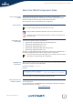
Chapter 8 Scenario 2: Business user with TOS marking. 8 Scenario 2: Business user with TOS marking. Introduction In this chapter we will explain on how IP QoS for a business user can be configured. In our example we will use the following configuration: Expected result On the LAN three groups of devices "Gold", "Silver" and "Bronze". Some Expedited Forwarding applications. The CPE is remotely managed.
Chapter 8 Scenario 2: Business user with TOS marking. Configuration The illustration below helps us to visualise e the setup. We will use three different LAN segements. 1 The “GOLD” segment using IP adresses in the range of 10.0.0.0/24. 2 The “SILVER”segment using IP adresses in the range of 11.0.0.0/24. 3 The “BRONZE” segment using IP adresses in the range of 12.0.0.0/24.
Chapter 8 Scenario 2: Business user with TOS marking. 8.1 Labels Label configuration We will now have a look at the labels that we will need. We have five different classes of traffic, which means that we will need 5 labels: 1 A VoIP label for voice traffic. 2 A Management label for management traffic. 3 A Gold label for traffic comming from the Gold Group. 4 A Silver label for traffic comming from the Silver Group. 5 A Bronze label for traffic comming from the Bronze Group.
Chapter 8 Scenario 2: Business user with TOS marking.
Chapter 8 Scenario 2: Business user with TOS marking. Silver label To create a label called Silver proceed as followed: 1 On the Label page click new at the bottom. You will now get a configuration screen at the bottom of the page. 2 Set the label name to SILVER. 3 Set classification to overwrite. 4 Set class to 9. 5 Set TCP ack class to 9. 6 Set Marking to DSCP. 7 Set the DSCP value to af21. 8 Click Apply to add the label to the list. The label name can be any chosen name.
Chapter 8 Scenario 2: Business user with TOS marking. Bronze label To create a label called Silver proceed as followed: 1 On the Label page click new at the bottom. You will now get a configuration screen at the bottom of the page. 2 Set Label name to BRONZE. 3 Set classification to overwrite. 4 Set class to 4. 5 Set TCP ack class to 4. 6 Set Marking to DSCP. 7 Set the DSCP value to cs0. 8 Click Apply to add the label to the list. 9 Click Save All to save the newly added labels.
Chapter 8 Scenario 2: Business user with TOS marking. 8.2 Rules. Rules configuration We will now have a look at the rules that we will need. We will need 8 rules: Two VoIP rules for voice traffic. (SIP and H323). Three Management rules for management traffic. (DNS,ICMP and IKE) One Gold rule for traffic comming from the Gold Group. One Silver rule for traffic comming from the Silver Group. One Bronze rule for traffic comming from the Bronze Group. As we have seen in “5.1.
Chapter 8 Scenario 2: Business user with TOS marking. VoIP rules We will now add the two VoIP rules to the QoS_user_rule list. Go to the Classification page and select the IP QoS Rules tab. Expert mode -> IP Router -> Classification Then proceed as followed: 1 Click New. You will now be able to add a new rule. 2 Set Index to1. 3 Set Name to VoIP. 4 Set Label to VoIP. 5 Set Service to sip. 6 Set Source interface to any. 7 Set Source IP to any. 8 Set Destination IP to any.
Chapter 8 Scenario 2: Business user with TOS marking. A second rule needs to be defined for VoIP. This rule will be used for voice packets using the H323 protocol. To do so proceed as followed: 1 Click the New. You will now be able to add a new rule. 2 Set Index to 2. 3 Set Name to VoIP2. 4 Set Label to VoIP. 5 Set Service to h323. 6 Set Source interface to any. 7 Set Source IP to any. 8 Set Destination IP to any. 9 Set State to selected.
Chapter 8 Scenario 2: Business user with TOS marking. Management rules Now we will add the three Management rules to the QoS_user_rule list. To do so proceed as followed: 1 Click New . You will now be able to add a new rule. 2 Set Index to 3. 3 Set Name to mngmt1. 4 Set Label to Management. 5 Set Service to dns. 6 Set Source interface to any. 7 Set Source IP to any. 8 Set Destination IP to any. 9 Set State to selected. 10 Click Apply to add the rule to the QoS_user_rules list.
Chapter 8 Scenario 2: Business user with TOS marking. A second rule needs to be defined for Management. This rule will be used for management packets using the ICMP protocol. 1 Click New. You will now be able to add a new rule. 2 Set Index to 4. 3 Set Name to mngmt2. 4 Set Label to Management. 5 Set Service to icmp. 6 Set Source interface to any. 7 Set Source IP to any. 8 Set Destination IP to any. 9 Set State to selected. 10 Click Apply to add the rule to the QoS_user_rules list.
Chapter 8 Scenario 2: Business user with TOS marking. A third rule needs to be defined for Management. This rule will be used for management packets using the IKE protocol. 1 Click New. You will now be able to add a new rule. The following values need to be configured: 1 Set Index to 5. 2 Set Name to mngmt3. 3 Set Label to Management. 4 Set Service to ike. 5 Set Source interface to any. 6 Set Source IP to any. 7 Set Destination IP to any. 8 Set State to selected.
Chapter 8 Scenario 2: Business user with TOS marking. Gold rule We will now continue by adding the Gold rule to the QoS_user_rule list. Proceed as followed: 1 Click New. You will now be able to add a new rule. 2 Set Index to 6. 3 Set Name to GOLD. 4 Set Label to GOLD. 5 Set Service to any. 6 Set Source interface to _lan1. 7 Set Source IP to any. 8 Set Destination IP to any. 9 Set State to selected. Click the Apply to add the rule to the QoS_user_rules list. E-NIT-CTC-20041213-0013 v0.
Chapter 8 Scenario 2: Business user with TOS marking. Silver rule We will now continue by adding the Silver rule to the QoS_user_rule list. Proceed as followed: 1 Click New. You will now be able to add a new rule. 2 Set Index to 7. 3 Set Name to SILVER. 4 Set Label to SILVER. 5 Set Service to any. 6 Set Source interface to _lan2. 7 Set Source IP to any. 8 Set Destination IP to any. 9 Set State to selected. 10 Click Apply to add the rule to the QoS_user_rules list.
Chapter 8 Scenario 2: Business user with TOS marking. Bronze rule We will now continue by adding the Bronze rule to the QoS_user_rule list. Proceed as followed: 1 Click New. You will now be able to add a new rule. 2 Set Index to 8. 3 Set Name to BRONZE. 4 Set Label to BRONZE. 5 Set Service to any. 6 Set Source interface to _lan3. 7 Set Source IP to any. 8 Set Destination IP to any. 9 Set State to selected. 10 Click Apply to add the rule to the QoS_user_rules list.
Chapter 8 Scenario 2: Business user with TOS marking. 8.3 IPQoS per PVC Introduction Now we need to enable IPQoS on the PVC used to access the internet. In our scenario we will use atm_pvc_0_35 to access the internet. Procedure Proceed as followed: Go to the IP QoS page and select the Configuration tab. Expert mode -> IP Router -> IP QoS.
Chapter 8 Scenario 2: Business user with TOS marking. Queues As seen in the introduction we will need an overflow of packets in the real time queue to a lower priority queue (WFQ4)when the EF traffic is exceeding 50% of the bandwidth. To do so proceed as followed: 1 Go to the IP QoS page and select the Queues tab Expert mode -> IP Router -> IP QoS You will now see a list of all queues per PVC.
Chapter 8 Scenario 2: Business user with TOS marking. 114 E-NIT-CTC-20041213-0013 v0.
Chapter 9 Scenario 3: Metering 9 Scenario 3: Metering Introduction To explain interface base metering we will take the setup from the previous scenario. The total upload bandwidth availlable for this scenario is 512Kbps. We reserved 50% of this bandwidth for EF traffic, meaning 256Kbps. Now we would like to limit the bandwidth availlable for the Bronze group to 64Kbps. Configuration To configure this meter proceed as followed: 1 Go to the IP QoS page and select the Meter tab.
Chapter 9 Scenario 3: Metering We now have a meter configured which will limit the upload bandwidth for the Bronze group to 64Kbps. We still need to start the meter. To do so proceed as followed: 1 Check the status check box. 2 Click Save All to save the changes made. As you can see in the configuration screen of the meter, metering can also be done label based. 116 E-NIT-CTC-20041213-0013 v0.
Reference List Reference List RFC791 INTERNET PROTOCOL. RFC2475 An Architecture for Differentiated Services. RFC1812 Requirements for IP Version 4 Routers. RFC3140 Per Hop Behavior Identification Codes. RFC3168 The Addition of Explicit Congestion Notification (ECN) to IP. RFC3246 An Expedited Forwarding PHB (Per-Hop Behaviour). RFC3247 Supplemental Information for the New Definition of the EF PHB (Expedited Forwarding Per-Hop Behavior). RFC2597 Assured Forwarding PHB Group.
Reference List 118 E-NIT-CTC-20041213-0013 v0.
Abreviation List Abreviation List ABR AF ATM BA CBR CE CDVT Available Bit Rate Assured Forwarding Asynchronous Transfer Mode Behavior Agregate Constant Bit Rate Congestion Experienced Cell Delay Variation Tolerance CLI Command Line Interface CS Class Selector DoS DSCP Denial of Service Differentiated Services Code Point ECN Explicit Congestion Notification ECT ECN-Capable Transport EF Expedited Forwarding GFR Generalized Frame Rate GUI Graphical User Interface IETF Internet Engineering T
Abreviation List 120 E-NIT-CTC-20041213-0013 v0.
© THOMSON 2005. All rights reserved. E-NIT-CTC-20041213-0013 v0.5 . Need more help? Additional help is available online at www.speedtouch.