
User's Manual

English
3
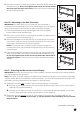
Part 1B – Mounting to the Wall (Concrete)
IMPORTANT! For safety reasons, the concrete wall must be capable of
supporting the combined weight of the mount and the display. The manufacturer
takes no responsibility for failure caused by walls of insuffi cient strength.
1. Place the appropriate mounting template against the wall in the desired
location. Make sure the template is level.
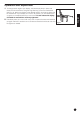
2. Drill four 8 mm (5/16”) holes in the wall using the template as a guide. Remove
any excess dust from the holes (see Fig. 4).
3. Remove the template from the wall and insert a concrete anchor (C) into each
hole so that it is fl ush with the concrete surface (see Fig. 5). A hammer can be
used to lightly tap the anchors into place if necessary.
NOTE: If the concrete wall is covered by a layer of plaster or drywall, the
concrete anchor must pass completely through the layer to rest fl ush with the
concrete surface.
4. Place the assembled wall plate against the wall over the inserted anchors and
attach it using the M6.3 x 63 screws (A) and washers (B) provided (see Fig. 6).
Do not over-tighten these screws and do not release the mount until all
screws are in place. Ensure that the mount remains level after all screws are
secured.
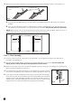
Part 2 – Attaching the Mount Arms to the Display
IMPORTANT! Use extra care during this part of the installation. If possible, avoid placing your display facedown
as it may damage the viewing surface.
NOTE: This mount comes with a selection of different screw diameters and lengths to accommodate a wide variety
of display models. Not all of the hardware in the kit will be used. If you cannot fi nd the appropriate screw size in the
kit provided, consult the manufacturer of your display for more information.
1. Determine the correct length of screw to use by examining the back of your display:
A. If the back of your display is fl at and the mounting holes are fl ush with the surface, you will use the shorter
screws (D or F) from the hardware kit.
B. If the back of your display is curved, has a protrusion, or if the mounting holes are recessed, you will need
to use the longer screws (E or G) and may also need to use the spacers (I).
2. Determine the correct diameter of screw to use by carefully trying one of each size (M6 and M8) from the
hardware kit. Do not force any of the screws – if you feel resistance stop immediately and try a smaller
diameter screw.
Fig.3
Fig.4
Fig.5
Fig.6
Continues on next page...
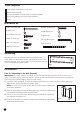
5. Attach the wall plate to the wall using the M6.3 x 63 screws (A) and washers (B)
provided (see Fig. 3). Do not over-tighten these screws and do not release
the mount until all screws are in place. Ensure that the mount remains level
after all screws are secured.